STEVAL-ISB001V1 STMicroelectronics, STEVAL-ISB001V1 Datasheet - Page 16
STEVAL-ISB001V1
Manufacturer Part Number
STEVAL-ISB001V1
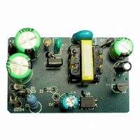
Description
BATTERY CHARGER CELL PHONE
Manufacturer
STMicroelectronics
Type
Battery Managementr
Specifications of STEVAL-ISB001V1
Main Purpose
Power Management, Battery Charger
Embedded
No
Utilized Ic / Part
STD1LNK60Z
Primary Attributes
1 Cell, 4.7V @ 400mA Out, CV/CC, 85 ~ 265VAC Input, 1.9W
Secondary Attributes
>65% Efficient, 51 ~ 91mW Standby Input Power
Input Voltage
85 V to 265 V
Output Voltage
5 V
Product
Power Management Modules
Silicon Manufacturer
ST Micro
Silicon Core Number
STD1LNK60Z-1
Kit Application Type
Power Management - Battery
Application Sub Type
Battery Charger
Kit Contents
Board
Rohs Compliant
No
Lead Free Status / RoHS Status
Lead free / RoHS Compliant
For Use With/related Products
STD1LNK60Z
Other names
497-5682
Available stocks
Company
Part Number
Manufacturer
Quantity
Price
Company:

Part Number:
STEVAL-ISB001V1
Manufacturer:
STMicroelectronics
Quantity:
1


2 STD1LNK60Z-based RCC Control Circuit Components
2.6
16/26
Note: R11>> R9 >> R7, so in this case, only R
Note: Constant control accuracy is not as good if Z1 is not used, and applying it is very simple.
For the purposes of this application design:
C
R
Zero Current Sense
C
through starting up resistor until MOSFET turns on for the first time. The MOSFET C
capacitor C
more than that of C
6.8nF.
R
expressed as
where,
V
N
N
V
V
N
V
I
Note: If a 20V external zener diode is used and the maximum current of the zener diode is
10mA, the value of R
R
R
R
ZD
o
DC(max)
F
ZD
7
11
5
10
a
p
s
10
12
12
= Optocoupler voltage
blocks DC current during starting up and allow charge to be delivered from the input voltage
= Fly-back voltage
= Secondary Winding Turns
= 4.7nF, and
= Auxiliary Winding Turns
= Primary Winding Turns
= Zener diode current
= 36K
limits power dissipation of zener diode inside the MOSFET. The selection process is
= 1.5K
limits current I
= 1K
= Zener diode voltage
= Maximum input bus voltage
iss
form a voltage divider at the MOSFET gate, so C
e
iss
of PC817, so the value of R
10
R
. This decreases the MOSFET (full) turn-on delay. In this case, C
R
10
7
is:
V
------------- -
L
=
DC
p
⎛
⎜
⎝
------------------------------------------------------------------------------------------------------
T
V
------------------------------------
d
DC m ax
N
---------------------- -
-------------------------------------------------------------------------------------- -
N
a
p
N
V
p
DC
N
a
+
+
N
------------------------------------- -
---------------------------------- -
I
a
ZD
R
V
o
11
V
11
N
12
+
o
N
is used:
s
+
V
is:
s
V
F
F
N
–
a
⎞
⎟
⎠
V
–
z 1
AN2228 - APPLICATION NOTE
V
R
ZD
9
5
value should be ten times
5
and input
5
=
Related parts for STEVAL-ISB001V1
Image
Part Number
Description
Manufacturer
Datasheet
Request
R

Part Number:
Description:
BOARD RGB CTR ST7,STP08C596MTR
Manufacturer:
STMicroelectronics
Datasheet:

Part Number:
Description:
Power Management IC Development Tools Full Speed USB to RS232 Bridge Demo
Manufacturer:
STMicroelectronics
Datasheet:
Part Number:
Description:
Power Management IC Development Tools 2.5W solar eval BRD USB SPV1040 LD39050
Manufacturer:
STMicroelectronics
Datasheet:

Part Number:
Description:
BOARD EVAL FOR MEMS SENSORS
Manufacturer:
STMicroelectronics
Datasheet:

Part Number:
Description:
KIT DEV STARTER ST10F276Z5
Manufacturer:
STMicroelectronics
Datasheet:

Part Number:
Description:
BOARD EVAL HDMI $ VIDEO SWITCH
Manufacturer:
STMicroelectronics
Datasheet:

Part Number:
Description:
BOARD DEMO ACCELEROMETER DIL24
Manufacturer:
STMicroelectronics
Datasheet:

Part Number:
Description:
BOARD STLM75/STDS75/ST72F651
Manufacturer:
STMicroelectronics
Datasheet:

Part Number:
Description:
EVAL BOARD 3AXIS MEMS ACCELLRMTR
Manufacturer:
STMicroelectronics
Datasheet:

Part Number:
Description:
BOARD EVAL 8BIT MICRO + TDE1708
Manufacturer:
STMicroelectronics
Datasheet:
Part Number:
Description:
STMicroelectronics [RIPPLE-CARRY BINARY COUNTER/DIVIDERS]
Manufacturer:
STMicroelectronics
Datasheet:
Part Number:
Description:
STMicroelectronics [LIQUID-CRYSTAL DISPLAY DRIVERS]
Manufacturer:
STMicroelectronics
Datasheet:
Part Number:
Description:
BOARD EVAL FOR MEMS SENSORS
Manufacturer:
STMicroelectronics
Datasheet: