STEVAL-ISB001V1 STMicroelectronics, STEVAL-ISB001V1 Datasheet - Page 17
STEVAL-ISB001V1
Manufacturer Part Number
STEVAL-ISB001V1
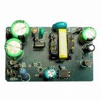
Description
BATTERY CHARGER CELL PHONE
Manufacturer
STMicroelectronics
Type
Battery Managementr
Specifications of STEVAL-ISB001V1
Main Purpose
Power Management, Battery Charger
Embedded
No
Utilized Ic / Part
STD1LNK60Z
Primary Attributes
1 Cell, 4.7V @ 400mA Out, CV/CC, 85 ~ 265VAC Input, 1.9W
Secondary Attributes
>65% Efficient, 51 ~ 91mW Standby Input Power
Input Voltage
85 V to 265 V
Output Voltage
5 V
Product
Power Management Modules
Silicon Manufacturer
ST Micro
Silicon Core Number
STD1LNK60Z-1
Kit Application Type
Power Management - Battery
Application Sub Type
Battery Charger
Kit Contents
Board
Rohs Compliant
No
Lead Free Status / RoHS Status
Lead free / RoHS Compliant
For Use With/related Products
STD1LNK60Z
Other names
497-5682
Available stocks
Company
Part Number
Manufacturer
Quantity
Price
Company:

Part Number:
STEVAL-ISB001V1
Manufacturer:
STMicroelectronics
Quantity:
1


AN2228 - APPLICATION NOTE
2.7
Constant Voltage And Constant Current
Two resistors, one 3.0
required power dissipation and resistance value.
Similarly, R15 limits the optocoupler’s I
compensates the constant current control.
For the purposes of this application, the devices are:
R
R
C
Note: The parameters of the remaining transformer devices can be seen in the Bill of Materials
(BOM, see
15
18
10
= 75 ,
= 360 , and
= 1nF.
The Constant Voltage (CV) configuration is comprised of the error amplifier TL431, R
R
voltage and compare it with the reference. C11 compensates the error amplifier TL431.
R19 limits the optocoupler diode current I
operation characteristics).
For the purposes of this application, the devices selected are:
R
R
C
R
The Constant Current (CC) can be established simply with a transistor, Q3, R16, R18,
R15, and C10. Output current flows through the sense resistor R16. Q3 is turned on when
the voltage drop of R16 reaches the same value as the base turn-on voltage of Q3. This
increases the current through the optocoupler and the converter goes into constant current
regulation.
R16 senses the output current, and R18 limits the base current of Q3. The rating power of
R16 must then be considered.
If I
22
21
22
11
19
o
, and C
=1k ;
=1k ;
=100nF; and
=150 .
= 0.4A and V
Appendix B: STD1LNK60Z-based RCC Circuit Bill of Materials
11
. TL431 provides the reference voltage. R21 and R22 divide the output
b
= 0.5V, then
and one 2.2 , with SMD1206 footprint are placed in parallel to get the
R
16
=
V
------ -
I
o
b
F
=
diode current for constant current regulation. C10
0.5
------- -
0.4
2 STD1LNK60Z-based RCC Control Circuit Components
F
=
(see
1.25
Figure 5
and
Figure 6 on page 18
).
for
21
17/26
,
Related parts for STEVAL-ISB001V1
Image
Part Number
Description
Manufacturer
Datasheet
Request
R

Part Number:
Description:
BOARD RGB CTR ST7,STP08C596MTR
Manufacturer:
STMicroelectronics
Datasheet:

Part Number:
Description:
Power Management IC Development Tools Full Speed USB to RS232 Bridge Demo
Manufacturer:
STMicroelectronics
Datasheet:
Part Number:
Description:
Power Management IC Development Tools 2.5W solar eval BRD USB SPV1040 LD39050
Manufacturer:
STMicroelectronics
Datasheet:

Part Number:
Description:
BOARD EVAL FOR MEMS SENSORS
Manufacturer:
STMicroelectronics
Datasheet:

Part Number:
Description:
KIT DEV STARTER ST10F276Z5
Manufacturer:
STMicroelectronics
Datasheet:

Part Number:
Description:
BOARD EVAL HDMI $ VIDEO SWITCH
Manufacturer:
STMicroelectronics
Datasheet:

Part Number:
Description:
BOARD DEMO ACCELEROMETER DIL24
Manufacturer:
STMicroelectronics
Datasheet:

Part Number:
Description:
BOARD STLM75/STDS75/ST72F651
Manufacturer:
STMicroelectronics
Datasheet:

Part Number:
Description:
EVAL BOARD 3AXIS MEMS ACCELLRMTR
Manufacturer:
STMicroelectronics
Datasheet:

Part Number:
Description:
BOARD EVAL 8BIT MICRO + TDE1708
Manufacturer:
STMicroelectronics
Datasheet:
Part Number:
Description:
STMicroelectronics [RIPPLE-CARRY BINARY COUNTER/DIVIDERS]
Manufacturer:
STMicroelectronics
Datasheet:
Part Number:
Description:
STMicroelectronics [LIQUID-CRYSTAL DISPLAY DRIVERS]
Manufacturer:
STMicroelectronics
Datasheet:
Part Number:
Description:
BOARD EVAL FOR MEMS SENSORS
Manufacturer:
STMicroelectronics
Datasheet: