STEVAL-IHM020V1 STMicroelectronics, STEVAL-IHM020V1 Datasheet - Page 16
STEVAL-IHM020V1
Manufacturer Part Number
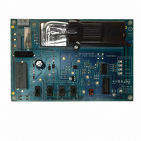
STEVAL-IHM020V1
Description
BOARD DEMO STCC08 AC SW DETECTOR
Manufacturer
STMicroelectronics
Type
Motor / Motion Controllers & Driversr
Specifications of STEVAL-IHM020V1
Main Purpose
Power Management, Triac Controller
Embedded
Yes, MCU, 8-Bit
Utilized Ic / Part
STCC08, ST7FLITE39F2
Primary Attributes
AC Switch Driver with Failure Mode Detector
Secondary Attributes
4 Toggle Switches for Failure Simulation, Capacitive Power Supply
Input Voltage
5 V
Product
Power Management Modules
Silicon Manufacturer
ST Micro
Silicon Core Number
STCC08
Kit Application Type
Power Management
Application Sub Type
AC Switch Failure Mode Detector
Kit Contents
Board Docs
Lead Free Status / RoHS Status
Lead free / RoHS Compliant
For Use With/related Products
ST7LITE39F2
Other names
497-8403
Available stocks
Company
Part Number
Manufacturer
Quantity
Price


IEC 61000-4-4 Burst immunity test
5
5.1
5.2
5.3
16/23
IEC 61000-4-4 Burst immunity test
Test conditions
●
●
●
Demonstration board immunity test
The AC line input X2 capacitor C15 (10 nF) is used to help avoid triggering the AC switch
(ACS108-6S). The MCU program reads the AVF signal at each AC line peak voltage (see
Figure
level for three consecutive AC line cycles.
Figure 12. AVF signal detection
The demonstration board and mains wires are placed 10 cm above the ground reference.
The mains wire is shorter than 1 m. Each operating cycle has been tested (load OFF and
ON). The burst withstanding level is higher than 4 kV without spurious triggering of the ACS
or ST7Lite3 MCU loss, whatever the coupling mode (to L, N, PE, etc.).
Recommendations for improving application immunity
To improve application EMC performance, the software must be EMC-oriented (for more
information please refer application note AN1015):
●
Ambient temperature: 25 °C
Relative humidity: 35%
Test performed in accordance with IEC 61000-4-4
Auto-recovery routine. At each RESET interrupt, the program must check if the data in
the RAM are stored as scheduled. Indeed, a RESET can occur without the supply
voltage having fallen below V
startup is not necessary, and the program can continue working with the previous RAM
ZVS
12). The AC switch state detection is deducted if the AVF signal remains at the same
ZVS delay
ZVS detection => TIMER ON
TIMER
> T/4 ms
READ AVF and TIMER OFF
T/2 ms
RM
(data retention parameter). In this case, a complete
ZVS delay
ZVS detection => TIMER ON
READ AVF and TIMER OFF
V
AC
UM0583
AM00149v1
Related parts for STEVAL-IHM020V1
Image
Part Number
Description
Manufacturer
Datasheet
Request
R

Part Number:
Description:
BOARD EVAL FOR MEMS SENSORS
Manufacturer:
STMicroelectronics
Datasheet:

Part Number:
Description:
KIT DEV STARTER ST10F276Z5
Manufacturer:
STMicroelectronics
Datasheet:

Part Number:
Description:
BOARD EVAL HDMI $ VIDEO SWITCH
Manufacturer:
STMicroelectronics
Datasheet:

Part Number:
Description:
BOARD DEMO ACCELEROMETER DIL24
Manufacturer:
STMicroelectronics
Datasheet:

Part Number:
Description:
BOARD STLM75/STDS75/ST72F651
Manufacturer:
STMicroelectronics
Datasheet:

Part Number:
Description:
EVAL BOARD 3AXIS MEMS ACCELLRMTR
Manufacturer:
STMicroelectronics
Datasheet:

Part Number:
Description:
BOARD EVAL 8BIT MICRO + TDE1708
Manufacturer:
STMicroelectronics
Datasheet:

Part Number:
Description:
EVAL BOARD A/D TS4657
Manufacturer:
STMicroelectronics
Datasheet:

Part Number:
Description:
BOARD ADAPTER 20DIP LIS3LV02DL
Manufacturer:
STMicroelectronics
Datasheet:

Part Number:
Description:
BOARD DEMO STM8S207R6/LIS331DLH
Manufacturer:
STMicroelectronics
Datasheet:

Part Number:
Description:
STMicroelectronics [RIPPLE-CARRY BINARY COUNTER/DIVIDERS]
Manufacturer:
STMicroelectronics
Datasheet:
Part Number:
Description:
STMicroelectronics [LIQUID-CRYSTAL DISPLAY DRIVERS]
Manufacturer:
STMicroelectronics
Datasheet:
Part Number:
Description:
BOARD EVAL FOR MEMS SENSORS
Manufacturer:
STMicroelectronics
Datasheet: