STEVAL-IHM020V1 STMicroelectronics, STEVAL-IHM020V1 Datasheet - Page 5
STEVAL-IHM020V1
Manufacturer Part Number
STEVAL-IHM020V1
Description
BOARD DEMO STCC08 AC SW DETECTOR
Manufacturer
STMicroelectronics
Type
Motor / Motion Controllers & Driversr
Specifications of STEVAL-IHM020V1
Main Purpose
Power Management, Triac Controller
Embedded
Yes, MCU, 8-Bit
Utilized Ic / Part
STCC08, ST7FLITE39F2
Primary Attributes
AC Switch Driver with Failure Mode Detector
Secondary Attributes
4 Toggle Switches for Failure Simulation, Capacitive Power Supply
Input Voltage
5 V
Product
Power Management Modules
Silicon Manufacturer
ST Micro
Silicon Core Number
STCC08
Kit Application Type
Power Management
Application Sub Type
AC Switch Failure Mode Detector
Kit Contents
Board Docs
Lead Free Status / RoHS Status
Lead free / RoHS Compliant
For Use With/related Products
ST7LITE39F2
Other names
497-8403
Available stocks
Company
Part Number
Manufacturer
Quantity
Price


UM0583
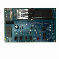
Components on the demonstration board include:
●
●
●
●
●
●
●
●
●
●
●
●
●
●
For more detailed information, please refer to the schematic diagram in
the STCC08 device (U1)
the STLITE39F2 MCU (U2). The 8-bit MCU drives the AC switch through the STCC08,
analyzes the STCC08 AVF signals and powers LEDs to indicate AC switch failures
the ACS108-6S (U3), transient voltage protected AC switch
A capacitive DC power supply
An ICC (in-circuit connector) (J3) to load the firmware in the MCU.
A switch to simulate an AC load failure in open circuit (SW1)
2 switches (SW2, SW3) to simulate a diode mode failure in both polarities of the AC line
and a short-circuit of the AC switch (when SW2 and SW3 are in the “YES” position at
the same time)
A switch to simulate an AC switch failure in open circuit (SW4)
An STCC08 CNTRL switch (SW5). This switch is used to turn the AC switch (ACS) on
or off through the MCU and the STCC08
An STCC08 CNTRL LED (D5), used to see whether or not the AC switch has been
controlled by the user
LEDs to define the ACS state
–
–
–
–
Test points to allow the connection of voltage probes:
–
–
–
–
–
–
–
–
–
An AC line connector (J1)
An AC load: light bulb (15 W at 230 V
Warning:
A “DIODE” LED (D6) to visualize an ACS failure in diode mode in both AC line
cycles. The LED is on if the AC switch fails in diode mode.
An “OPEN” LED (D7) to indicate an ACS failure in open circuit. This LED is on if
the AC switch is damaged in open circuit
A “CC” LED (D8) to show an ACS failure in short-circuit on both polarities of the
AC line. This LED is on if the AC switch is damaged in short-circuit
An “ON” LED (D9) to indicate that the AC switch is on
L (TP2) and N (TP1): line and neutral of the AC line
VCC (TP3): positive power supply
GND (TP4): power supply reference
ZVS (TP5): zero crossing of the AC line voltage
OUT (TP6): anode of the ACS
AC (TP7): ACS status sense input
AVF (TP8): alternating voltage feedback. ACS status output
ON/OFF (TP12): “STCC08 CNTRL” switch state, used to turn on or off the ACS
through the MCU and the STCC08
IN (TP9): STCC08 IN input used to control the ACS
Before the board is connected to a computer through the ICC
connector, ensure that the AC line is connected to the board
through an insulated plug. This is essential to avoid electrical
shock.
RMS
).
Demonstration board introduction
Appendix
A.
5/23
Related parts for STEVAL-IHM020V1
Image
Part Number
Description
Manufacturer
Datasheet
Request
R

Part Number:
Description:
BOARD EVAL FOR MEMS SENSORS
Manufacturer:
STMicroelectronics
Datasheet:

Part Number:
Description:
KIT DEV STARTER ST10F276Z5
Manufacturer:
STMicroelectronics
Datasheet:

Part Number:
Description:
BOARD EVAL HDMI $ VIDEO SWITCH
Manufacturer:
STMicroelectronics
Datasheet:

Part Number:
Description:
BOARD DEMO ACCELEROMETER DIL24
Manufacturer:
STMicroelectronics
Datasheet:

Part Number:
Description:
BOARD STLM75/STDS75/ST72F651
Manufacturer:
STMicroelectronics
Datasheet:

Part Number:
Description:
EVAL BOARD 3AXIS MEMS ACCELLRMTR
Manufacturer:
STMicroelectronics
Datasheet:

Part Number:
Description:
BOARD EVAL 8BIT MICRO + TDE1708
Manufacturer:
STMicroelectronics
Datasheet:

Part Number:
Description:
EVAL BOARD A/D TS4657
Manufacturer:
STMicroelectronics
Datasheet:

Part Number:
Description:
BOARD ADAPTER 20DIP LIS3LV02DL
Manufacturer:
STMicroelectronics
Datasheet:

Part Number:
Description:
BOARD DEMO STM8S207R6/LIS331DLH
Manufacturer:
STMicroelectronics
Datasheet:

Part Number:
Description:
STMicroelectronics [RIPPLE-CARRY BINARY COUNTER/DIVIDERS]
Manufacturer:
STMicroelectronics
Datasheet:
Part Number:
Description:
STMicroelectronics [LIQUID-CRYSTAL DISPLAY DRIVERS]
Manufacturer:
STMicroelectronics
Datasheet:
Part Number:
Description:
BOARD EVAL FOR MEMS SENSORS
Manufacturer:
STMicroelectronics
Datasheet: