NCP345EVB ON Semiconductor, NCP345EVB Datasheet - Page 5
NCP345EVB
Manufacturer Part Number
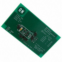
NCP345EVB
Description
EVAL BOARD FOR NCP345
Manufacturer
ON Semiconductor
Specifications of NCP345EVB
Design Resources
NCP345 Demo Board BOM NCP345EVB Gerber Files NCP345/6 EVB Schematic
Main Purpose
Overvoltage Protection
Embedded
No
Utilized Ic / Part
NCP345
Lead Free Status / RoHS Status
Lead free / RoHS Compliant
Secondary Attributes
-
Primary Attributes
-
Lead Free Status / Rohs Status
Lead free / RoHS Compliant
For Use With/related Products
NCP345
Other names
NCP345EVBOS


Introduction
adapter is used to convert the AC line voltage into a
regulated DC voltage or a current limited source. Line
surges or faults in the adapter may result in overvoltage
events that can damage sensitive electronic components
within the product. This is becoming more critical as the
operating voltages of many integrated circuits have been
lowered due to advances in sub−micron silicon lithography.
In addition, portable products with removable battery packs
pose special problems since the pack can be removed at any
time. If the user removes a pack in the middle of charging,
a large transient voltage spike can occur which can damage
the product. Finally, damage can result if the user plugs in
the wrong adapter into the charging jack. The challenge of
the product designer is to improve the robustness of the
design and avoid situations where the product can be
damaged due to un−expected, but unfortunately, likely
events that will occur as the product is used.
Circuit Overview
has been developed consisting of the NCP345 Over Voltage
Protection IC and a P−channel MOSFET switch such as the
MGSF3441. The NCP345 monitors the input voltage and
will not turn on the MOSFET unless the input voltage is
within a safe operating window that has an upper limit of
7.05 V. A zener diode can be placed in parallel to the load to
provide for secondary protection during the brief time that
it takes for the NCP345 to detect the overvoltage fault and
disconnect the MOSFET. The decision to use this secondary
diode is a function of the charging currents expected, load
capacitance across the battery, and the desired protection
In many electronic products, an external AC/DC wall
To address these problems, the protection system above
Accessory Charger
AC/DC Adapter or
(optional)
Zener
Diode
IN
GND
APPLICATION INFORMATION
V
+
−
ref
http://onsemi.com
Undervoltage
V
CC
Lock Out
Figure 8.
Logic
NCP345
5
CNTRL
Microprocessor
voltage by analyzing the dV/dT rise that occurs during the
brief time it takes to turn−off the MOSFET. For battery
powered applications, a low−forward voltage Schottky
diode such as the MBRM120LT3 can be placed in series
with the MOSFET to block the body diode of the MOSFET
and prevent shorting the battery out if the input is
accidentally shorted to ground. This provides additional
voltage margin at the load since there is a small forward drop
across this diode that reduces the voltage at the load.
can be a sudden rise in the input voltage of the device. This
transient can be quite large depending on the impedance of
the supply and the current being drawn from the supply at the
time of an overvoltage event. This inductive spike can be
clamped with a zener diode from IN to ground. This diode
breakdown voltage should be well above the worst case
supply voltage provided from the AC/DC adapter or
Cigarette Lighter Adapter (CLA), since the zener is only
intended to clamp the transient. The NCP345 is designed so
that the IN and V
withstand transients to 30 V. Since these spikes can be very
narrow in duration, it is important to use a high bandwidth
probe and oscilloscope when prototyping the product to
verify the operation of the circuit under all the transient
conditions. A similar problem can result due to contact
bounce as the DC source is plugged into the product.
ground in parallel with the battery. If the product has a
battery pack that is easily removable during charging, this
scenario should be analyzed. Under that situation, the
charging current will go into the capacitor and the voltage
may rise rapidly depending on the capacitor value, the
charging current and the power supply response time.
NCP345
Driver
FET
port
When the protection circuit turns off the MOSFET, there
For portable products it is normal to have a capacitor to
OUT
P−CH
(optional)
CC
Zener
Diode
pin can safely protect up to 25 V and
Schottky
Diode
+
C1
LOAD
Related parts for NCP345EVB
Image
Part Number
Description
Manufacturer
Datasheet
Request
R

Part Number:
Description:
ON Semiconductor [VOLTAGE REGULATOR]
Manufacturer:
ON Semiconductor
Datasheet:
Part Number:
Description:
357-036-542-201 CARDEDGE 36POS DL .156 BLK LOPRO
Manufacturer:
ON Semiconductor
Datasheet:
Part Number:
Description:
357-036-542-201 CARDEDGE 36POS DL .156 BLK LOPRO
Manufacturer:
ON Semiconductor
Datasheet:
Part Number:
Description:
357-036-542-201 CARDEDGE 36POS DL .156 BLK LOPRO
Manufacturer:
ON Semiconductor
Datasheet:
Part Number:
Description:
357-036-542-201 CARDEDGE 36POS DL .156 BLK LOPRO
Manufacturer:
ON Semiconductor
Datasheet:
Part Number:
Description:
357-036-542-201 CARDEDGE 36POS DL .156 BLK LOPRO
Manufacturer:
ON Semiconductor
Datasheet:
Part Number:
Description:
357-036-542-201 CARDEDGE 36POS DL .156 BLK LOPRO
Manufacturer:
ON Semiconductor
Datasheet:
Part Number:
Description:
357-036-542-201 CARDEDGE 36POS DL .156 BLK LOPRO
Manufacturer:
ON Semiconductor
Datasheet:
Part Number:
Description:
357-036-542-201 CARDEDGE 36POS DL .156 BLK LOPRO
Manufacturer:
ON Semiconductor
Datasheet:
Part Number:
Description:
357-036-542-201 CARDEDGE 36POS DL .156 BLK LOPRO
Manufacturer:
ON Semiconductor
Datasheet:
Part Number:
Description:
357-036-542-201 CARDEDGE 36POS DL .156 BLK LOPRO
Manufacturer:
ON Semiconductor
Datasheet:
Part Number:
Description:
Manufacturer:
ON Semiconductor
Datasheet:
Part Number:
Description:
Manufacturer:
ON Semiconductor
Datasheet: