MCP355XDV-MS1 Microchip Technology, MCP355XDV-MS1 Datasheet - Page 16
MCP355XDV-MS1
Manufacturer Part Number
MCP355XDV-MS1
Description
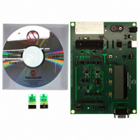
BOARD DEV SENSOR APP MCP355X
Manufacturer
Microchip Technology
Datasheets
1.MCP3553-ESN.pdf
(36 pages)
2.MCP355XDV-MS1.pdf
(36 pages)
3.MCP3551DM-PCTL.pdf
(30 pages)
Specifications of MCP355XDV-MS1
Number Of Adc's
1
Number Of Bits
22
Data Interface
Serial
Inputs Per Adc
1 Differential
Input Range
±0.3 V
Voltage Supply Source
Single Supply
Operating Temperature
-40°C ~ 125°C
Utilized Ic / Part
MCP355x
Processor To Be Evaluated
MCP355x
Interface Type
RS-232, USB
Lead Free Status / RoHS Status
Not applicable / Not applicable
Lead Free Status / RoHS Status
Lead free / RoHS Compliant, Not applicable / Not applicable
Available stocks
Company
Part Number
Manufacturer
Quantity
Price
Company:

Part Number:
MCP355XDV-MS1
Manufacturer:
MICROCHIP
Quantity:
12 000


MCP355X Sensor Application Developer’s Board User’s Guide
2.5
DS51609A-page 12
BRIDGE SIMULATOR BOARDS
2.4.2
Channel 2 can also be used to evaluate the MCP355X in a direct-connect sensor
configuration. This is accomplished using the 14-pin dual row header JP2. Changing
the headers to DIRECT+ and DIRECT- will take the signal present on the channel input
header (P7) directly into the MCP355X. Figure 2-6 represents this circuit configuration
using channel 2.
FIGURE 2-6:
There are two small boards included with the MCP355X Sensor Application
Developer’s Board. These boards represent a simulation of an external wheatstone
bridge that is either at zero-scale or full-scale. These boards come populated with
resistors that have a temperature drift specification of 10 ppm/C. For the best bridge
simulation, it is recommended that the bridges be populated with very low drift resistors
with a tempco value of 0.1 ppm/C. Typical load cell bridges will exhibit this output
temperature drift. These boards can be plugged in to either P6 or P7 to assist in
eliminating any error associated with an external sensor. Figure 2-7 represents the
bridge simulator boards and how they should be connected to the MCP355X Sensor
Application Developer’s Board. Refer to Appendix A. “Schematic and Layouts” for
complete schematic.
FIGURE 2-7:
Channel 2 - Direct-Connect Applications (No Amplifier or Gain)
A Direct-connect Weigh Scale.
Bridge Simulator Boards.
Bridge Simulator Boards
R
1
V
V
IN
IN
+
-
MCP3551
V
DD
V
© 2006 Microchip Technology Inc.
V
REF
SS
P6 (
OR
P7)
C
-SENSE
-IN
-OUT
+OUT
+IN
+SENSE
1
Related parts for MCP355XDV-MS1
Image
Part Number
Description
Manufacturer
Datasheet
Request
R

Part Number:
Description:
Manufacturer:
Microchip Technology Inc.
Datasheet:
Part Number:
Description:
Manufacturer:
Microchip Technology Inc.
Datasheet:
Part Number:
Description:
Manufacturer:
Microchip Technology Inc.
Datasheet:
Part Number:
Description:
Manufacturer:
Microchip Technology Inc.
Datasheet:
Part Number:
Description:
Manufacturer:
Microchip Technology Inc.
Datasheet:
Part Number:
Description:
Manufacturer:
Microchip Technology Inc.
Datasheet:
Part Number:
Description:
Manufacturer:
Microchip Technology Inc.
Datasheet:
Part Number:
Description:
Manufacturer:
Microchip Technology Inc.
Datasheet: