MCP355XDV-MS1 Microchip Technology, MCP355XDV-MS1 Datasheet - Page 19
MCP355XDV-MS1
Manufacturer Part Number
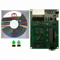
MCP355XDV-MS1
Description
BOARD DEV SENSOR APP MCP355X
Manufacturer
Microchip Technology
Datasheets
1.MCP3553-ESN.pdf
(36 pages)
2.MCP355XDV-MS1.pdf
(36 pages)
3.MCP3551DM-PCTL.pdf
(30 pages)
Specifications of MCP355XDV-MS1
Number Of Adc's
1
Number Of Bits
22
Data Interface
Serial
Inputs Per Adc
1 Differential
Input Range
±0.3 V
Voltage Supply Source
Single Supply
Operating Temperature
-40°C ~ 125°C
Utilized Ic / Part
MCP355x
Processor To Be Evaluated
MCP355x
Interface Type
RS-232, USB
Lead Free Status / RoHS Status
Not applicable / Not applicable
Lead Free Status / RoHS Status
Lead free / RoHS Compliant, Not applicable / Not applicable
Available stocks
Company
Part Number
Manufacturer
Quantity
Price
Company:

Part Number:
MCP355XDV-MS1
Manufacturer:
MICROCHIP
Quantity:
12 000


© 2006 Microchip Technology Inc.
In disabled mode, ZERO
direct ADC value (units = ADU), the output is simply the decimal representation of
ADC
displayed.
Pressing the HOLD button freezes the LCD display to allow for viewing in fast sampling
modes (less averaging). Pressing the HOLD button again will resume normal
operation.
3.2.2.2
In this menu, the user has control over which channel is being sampled. There are four
options. Pressing either F1 or F2 cycles through these options:
Channel 1 Normal
In this mode, the PIC16F877 samples the MCP3551 on channel 1. The LCD text above
F2 will display “1N”. In the normal mode, the analog switches on this channel are set
to the “positive” polarity. Refer to Chapter 2. “Hardware Description” for more
description on the analog switch sampling.
Channel 1 Inverted
In this mode, the analog switches set to reverse polarity, and the inverted ADC sample
is displayed on the LCD display. The LCD text above F2 will display “1I”. Refer to
Chapter 2. “Hardware Description” for more description on the analog switch
sampling.
Channel 1 Switched
In this mode, the PIC16F877 is switching back and forth between positive and reverse
polarity and the averaged value is displayed on the LCD display. The LCD text above
F2 will display “1S”. Refer to Chapter 2. “Hardware Description” for more description
on the analog switch sampling.
Channel 2
In this mode, the PIC16F877 is sampling channel 2. This channel is the high gain circuit
using amplifier CS3002. The resulting code is displayed on the LCD display.
3.2.2.3
There are three units: A/D Units (ADU), grams (g), or kilograms (kg). When in this
menu, pressing either F1 or F2 will change the text to the right of the numerical output
to the proper unit and also display the appropriate representation of the A/D sample.
3.2.2.4
In the averaging menu, the user can select how many samples are collected before the
value is applied to the LCD output. This averaging applies all sampling situations, i.e.
when calibrating zero, full scale, or displaying the output after calibration. The user can
select between 1 (no averaging), 2, 4, 8, or 16 averages. The output noise of the
system will be reduced by the square root of the number of averages per the equation
below.
EQUATION 3-2:
VAL
. If zero calibrate is enabled, then ZERO
CHANNEL SELECT
UNITS
AVERAGING
Where:
CAL
MCP3551 Output Noise
N = the number of conversions
is not subtracted per Equation 3-1. When displaying the
=
CAL
2.5 µV RMS
---------------------------- -
is subtracted before the value is
N
DS51609A-page 15
Related parts for MCP355XDV-MS1
Image
Part Number
Description
Manufacturer
Datasheet
Request
R

Part Number:
Description:
Manufacturer:
Microchip Technology Inc.
Datasheet:
Part Number:
Description:
Manufacturer:
Microchip Technology Inc.
Datasheet:
Part Number:
Description:
Manufacturer:
Microchip Technology Inc.
Datasheet:
Part Number:
Description:
Manufacturer:
Microchip Technology Inc.
Datasheet:
Part Number:
Description:
Manufacturer:
Microchip Technology Inc.
Datasheet:
Part Number:
Description:
Manufacturer:
Microchip Technology Inc.
Datasheet:
Part Number:
Description:
Manufacturer:
Microchip Technology Inc.
Datasheet:
Part Number:
Description:
Manufacturer:
Microchip Technology Inc.
Datasheet: