MCP355XDV-MS1 Microchip Technology, MCP355XDV-MS1 Datasheet - Page 18
MCP355XDV-MS1
Manufacturer Part Number
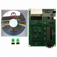
MCP355XDV-MS1
Description
BOARD DEV SENSOR APP MCP355X
Manufacturer
Microchip Technology
Datasheets
1.MCP3553-ESN.pdf
(36 pages)
2.MCP355XDV-MS1.pdf
(36 pages)
3.MCP3551DM-PCTL.pdf
(30 pages)
Specifications of MCP355XDV-MS1
Number Of Adc's
1
Number Of Bits
22
Data Interface
Serial
Inputs Per Adc
1 Differential
Input Range
±0.3 V
Voltage Supply Source
Single Supply
Operating Temperature
-40°C ~ 125°C
Utilized Ic / Part
MCP355x
Processor To Be Evaluated
MCP355x
Interface Type
RS-232, USB
Lead Free Status / RoHS Status
Not applicable / Not applicable
Lead Free Status / RoHS Status
Lead free / RoHS Compliant, Not applicable / Not applicable
Available stocks
Company
Part Number
Manufacturer
Quantity
Price
Company:

Part Number:
MCP355XDV-MS1
Manufacturer:
MICROCHIP
Quantity:
12 000


MCP355X Sensor Application Developer’s Board User’s Guide
DS51609A-page 14
3.2.2
The right most button F3 is the menu control button.
FIGURE 3-1:
and F3 buttons.
Pressing this button will cycle through the menu options and change the functionality
of the other two buttons, F1 and F2. The LCD text above the buttons describes the
functionality for the different menus.
Here are the LCD menus that can be selected using the F3 button:
• Zero Calibrate - Enable/Disable/Hold
• Channel Select
• Units
• Averaging
• Full-Scale Value Selection
• Full-Scale Calibration
There are four different menu options that will be described in individual sections.
3.2.2.1
When in this menu, the first button becomes the ZERO button. When this button is
selected, the most recent ADC value after averaging will be loaded into the ZERO
register.
Zero calibration is also enabled or disabled by pressing the ZERO button. This is
indicated by a change of the spinning character on the far top-right of the display, (i.e.:
a LINE is inserted under the spinning character when zero calibration is turned ON.)
When enabled, ZERO
FIGURE 3-2:
substraction in the calculation. The icon on the right has a bar underneath that
represents when zero subtraction is enabled.
.
Controlling the LCD Menu
ZERO CALIBRATE
LCD showing the Averaging Menu. Also shown are the F1, F2
These two icons show the presence of the zero offset
CAL
is subtracted as per Equation 3-1. Refer to Figure 3-2.
© 2006 Microchip Technology Inc.
CAL
Related parts for MCP355XDV-MS1
Image
Part Number
Description
Manufacturer
Datasheet
Request
R

Part Number:
Description:
Manufacturer:
Microchip Technology Inc.
Datasheet:
Part Number:
Description:
Manufacturer:
Microchip Technology Inc.
Datasheet:
Part Number:
Description:
Manufacturer:
Microchip Technology Inc.
Datasheet:
Part Number:
Description:
Manufacturer:
Microchip Technology Inc.
Datasheet:
Part Number:
Description:
Manufacturer:
Microchip Technology Inc.
Datasheet:
Part Number:
Description:
Manufacturer:
Microchip Technology Inc.
Datasheet:
Part Number:
Description:
Manufacturer:
Microchip Technology Inc.
Datasheet:
Part Number:
Description:
Manufacturer:
Microchip Technology Inc.
Datasheet: