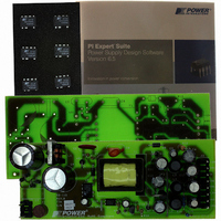
RDK-115 Power Integrations, RDK-115 Datasheet - Page 13

RDK-115
Manufacturer Part Number
RDK-115
Description
KIT REFERENCE DESIGN W/TN376PN
Manufacturer
Power Integrations
Series
TinySwitch®-PKr
Specifications of RDK-115
Main Purpose
AC/DC, Primary Side
Outputs And Type
4, Isolated
Power - Output
7.5W
Voltage - Output
3.3V, 5V, 12V, -12V
Current - Output
500mA, 500mA, 250mA, 30mA
Voltage - Input
85 ~ 265VAC
Regulator Topology
Flyback
Frequency - Switching
132kHz
Board Type
Fully Populated
Utilized Ic / Part
TNY376
Product
Accessories & Kits
Lead Free Status / RoHS Status
Not applicable / Not applicable
Other names
596-1145
7 Transformer Specification
7.1 Electrical Diagram
7.2 Electrical Specifications
7.3 Materials
Page 13 of 36
Primary Leakage Inductance
Resonant Frequency
Primary Inductance
Electrical Strength
Item
[10]
[11]
[12]
[1]
[2]
[3]
[4]
[5]
[6]
[7]
[8]
[9]
Core: EEL19, Nicera NC-2H or equiv. gapped for AL of 150 nH/T
Bobbin: EEL19 Horizontal 12 pins
Magnet Wire: # 28 AWG
Magnet Wire: # 29 AWG
Magnet Wire: # 26 AWG
Teflon Tubing # 22
Margin Tape: 3M # 44 Polyester web. 3.0 mm wide
Copper Foil 0.52 mm thick, 12 mm wide.
Tape for Copper 2.0 mils thick, 16 mm wide.
Tape: 3M 1298 Polyester Film, 12.8 mm wide
Tape: 3M 1298 Polyester Film, 18.2 mm wide
Varnish
Shield 1
Figure 4 – Transformer Electrical Diagram.
Primary
Bias
W2
W3
W1
6T x 4 # 29AWG
60Hz 1 second, from Pins 1-5 to Pins 6-12
74T # 29AWG
34T #28AWG
NC
1
4
3
5
1
Pin 1 to Pin 4, all other windings open
Pin 1 to Pin 4, all other windings open
Pin 1 to Pin 4, Pins 6-12 shorted
Measured at 132 kHz.
Description
7T x 2 #26AWG
4T x 2 #26AWG
1T
2T
Tel: +1 408 414 9200 Fax: +1 408 414 9201
Foil
Foil
11
8,9,10
12
6
7
W5
+3.3 V
+12 V
+5 V
-12 V
W6
W4
W7
Power Integrations
www.powerint.com
0.813 mH +/- 12%
300 kHz (Min.)
30 µH Max.
3000 V ac
2


