RDK-115 Power Integrations, RDK-115 Datasheet - Page 26
RDK-115
Manufacturer Part Number
RDK-115
Description
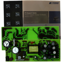
KIT REFERENCE DESIGN W/TN376PN
Manufacturer
Power Integrations
Series
TinySwitch®-PKr
Specifications of RDK-115
Main Purpose
AC/DC, Primary Side
Outputs And Type
4, Isolated
Power - Output
7.5W
Voltage - Output
3.3V, 5V, 12V, -12V
Current - Output
500mA, 500mA, 250mA, 30mA
Voltage - Input
85 ~ 265VAC
Regulator Topology
Flyback
Frequency - Switching
132kHz
Board Type
Fully Populated
Utilized Ic / Part
TNY376
Product
Accessories & Kits
Lead Free Status / RoHS Status
Not applicable / Not applicable
Other names
596-1145


11.3 Drain Voltage and Current Start-up Profile
Figure 20 – 85 VAC Input and Maximum Load.
11.4 Load Transient Response
In the figures shown below, signal averaging was used to better enable viewing the load
transient response. Since the output switching and line frequency occur essentially at
random with respect to the load transient, contributions to the output ripple from these
sources will average out, leaving the contribution only from the load step response.
Figure 22 – Transient Response, 115 VAC, +12 V
Upper: I
Lower: V
0.25 A-0.64 A-0.25 A Load Step. All
other outputs are at full load.
Bottom Trace: 5 V Output at 50 mV / div.
Next Trace: 3.3 V Output at 50 mV / div.
Next Trace: +12 V Output at 0.5 V / div.
Top Trace: -12 V Output at 0.5 V / div.
1 ms / div
Power Integrations
Tel: +1 408 414 9200 Fax: +1 408 414 9201
www.powerint.com
DRAIN
DRAIN
.
, 0.5 A / div.
, 100 V & 1 ms / div.
Figure 21 – 265 VAC Input and Maximum Load.
Figure 23 – Transient Response, 230 VAC, +12 V
Upper: I
Lower: V
0.25 A-0.64 A-0.25 A Load Step. All
other outputs are at full load.
Bottom Trace: 5V Output at 50 mV / div.
Next Trace: 3.3V Output at 50 mV / div.
Next Trace: +12 V Output at 0.5 V / div.
Top Trace: -12 V Output at 0.5 V / div.
1 ms / div.
DRAIN
DRAIN
, 0.5 A / div.
, 200 V & 1 ms / div.
Page 26 of 36
Related parts for RDK-115
Image
Part Number
Description
Manufacturer
Datasheet
Request
R

Part Number:
Description:
KIT REF DESIGN FOR LNK457D
Manufacturer:
Power Integrations
Datasheet:

Part Number:
Description:
REFERENCE DESIGN LINKSWITCH-PH
Manufacturer:
Power Integrations
Datasheet:

Part Number:
Description:
KIT REF DESIGN FOR LNK403EG
Manufacturer:
Power Integrations
Datasheet:

Part Number:
Description:
KIT REF DESIGN FOR LNK406EG
Manufacturer:
Power Integrations
Datasheet:

Part Number:
Description:
KIT REF DESIGN LINKSWITCH-CV
Manufacturer:
Power Integrations
Datasheet:

Part Number:
Description:
KIT REF DESIGN LINKSWITCH 2
Manufacturer:
Power Integrations
Datasheet:

Part Number:
Description:
Specifications: Family: Eval Boards - DC/DC & AC/DC (Off-Line) SMPS ; Series: HiperLCS™ ; Main Purpose: DC/DC, Step Down ; Outputs and Type: 1, Isolated ; Power - Output: 150W ; Voltage - Output: 24V ; Current - Output: 6.25A ; Voltage - Input:
Manufacturer:
Power Integrations, Inc.
Datasheet:

Part Number:
Description:
KIT DESIGN REF TINYSWITCH-III
Manufacturer:
Power Integrations
Datasheet:

Part Number:
Description:
KIT DESIGN REF LINKSWITCH LP
Manufacturer:
Power Integrations
Datasheet:

Part Number:
Description:
KIT REF DESIGN LED LINKSWITCH TN
Manufacturer:
Power Integrations
Datasheet:
Part Number:
Description:
KIT REF DESIGN PG LINKSWITCH-II
Manufacturer:
Power Integrations
Datasheet:
Part Number:
Description:
REFERENCE DESIGN LINKSWITCH-PL
Manufacturer:
Power Integrations
Datasheet:
Part Number:
Description:
REFERENCE DESIGN LINKSWITCH-PH
Manufacturer:
Power Integrations
Datasheet:

Part Number:
Description:
KIT REF DESIGN 36-72W MOTOR DRVR
Manufacturer:
Power Integrations
Datasheet:
Part Number:
Description:
Specifications: Manufacturer: Power Integrations ; Output Voltage: 380 VDC ; Input / Supply Voltage (Max): 264 VAC ; Input / Supply Voltage (Min): 90 VAC ; Mounting Style: Through Hole ; Output Current: 0.913 A ; Output Power: 347 W
Manufacturer:
Power Integrations, Inc.