RDK-115 Power Integrations, RDK-115 Datasheet - Page 15
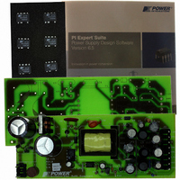
RDK-115
Manufacturer Part Number
RDK-115
Description
KIT REFERENCE DESIGN W/TN376PN
Manufacturer
Power Integrations
Series
TinySwitch®-PKr
Specifications of RDK-115
Main Purpose
AC/DC, Primary Side
Outputs And Type
4, Isolated
Power - Output
7.5W
Voltage - Output
3.3V, 5V, 12V, -12V
Current - Output
500mA, 500mA, 250mA, 30mA
Voltage - Input
85 ~ 265VAC
Regulator Topology
Flyback
Frequency - Switching
132kHz
Board Type
Fully Populated
Utilized Ic / Part
TNY376
Product
Accessories & Kits
Lead Free Status / RoHS Status
Not applicable / Not applicable
Other names
596-1145


7.6 Transformer Construction
Page 15 of 36
W7 -12 V output.
Basic Insulation
Basic Insulation
Basic Insulation
Basic Insulation
Outer Insulation
W2 Two Layers
+3.3 V and +5 V
Core Assembly
Final Assembly
Bobbin Set Up
W6 +12 V out
Margin Tape
Margin Tape
W1 Shield 1
Orientation
W4 and W5
Insulation
outputs.
W3 Bias
Primary
Set up the bobbin with pin #1 oriented to the left-hand side.
Apply 3.0 mm margin at each side of bobbin using item [7]. Match combined height
of primary, shield and bias windings.
Start with a floating lead temporary tie on pin 8. Wind 34 turns of item [3] from right
to left. Wind tightly and uniformly across entire width of bobbin. Finish at pin 1
using item [6] at the finish leads. Remove the wire from pin 8 and cut the starting
lead just at the starting of the winding.
Apply one layer of tape item [10].
Start on pin 1 using item [6] at the start leads. Wind 37 turns of item [4] from left to
right. Apply one layer of item [10]. Continue the same wire on second layer. Wind
37 turns from right to left. The two layers should be wound tightly with the turns
uniformly distributed across entire width of bobbin. Finish on pin 4 using item [6] at
the finish leads.
Apply one layer of tape item [10].
Start on pin 5 using item [6] at the start leads. Wind 6 turns of 4 parallel wires of
item [4]. Wind from left to right in a single layer. The wires should be tightly and
uniformly wound spread across the bobbin width. Finish on pin 3 using item [6] at
the finish leads.
Apply 3 Layers of tape [11] for insulation.
Apply 3.0 mm margin at each side of bobbin using item [7]. Match combines height
of secondary windings.
Prepare copper foil item [8] and item [9] as shown in figure 6. Start at pin 8,9,10
using item [6] at the start leads. Wind 2 turns. Connect the second lead to pin 7
using item [6] at the finish leads; wind 1 turn. Connect the end lead to pin 11 using
item [6] at the finish leads.
Apply one layer of tape item [10].
Start on pin 11 using item [6] at the start leads. Wind 4 turns of Bifilar wires of item
[5]. Wind from right to left in a single tightly wound spread across the bobbin width.
Finish on pin 6 using item [6] at the finish leads.
Apply one layer of tape item [10].
Start at pin 12 using item [6] at the start leads. Wind 7 turns of Bifilar wires of item
[5]. Wind from right to left in a uniform and tightly wound spread across the bobbin
width. Finish on pin 8,9,10 using item [6] at the finish leads.
2 Layers of tape [11] for insulation.
Assemble and secure core halves. Item [1]
Dip Varnish uniformly in item [12].
Tel: +1 408 414 9200 Fax: +1 408 414 9201
Power Integrations
www.powerint.com
Related parts for RDK-115
Image
Part Number
Description
Manufacturer
Datasheet
Request
R

Part Number:
Description:
KIT REF DESIGN FOR LNK457D
Manufacturer:
Power Integrations
Datasheet:

Part Number:
Description:
REFERENCE DESIGN LINKSWITCH-PH
Manufacturer:
Power Integrations
Datasheet:

Part Number:
Description:
KIT REF DESIGN FOR LNK403EG
Manufacturer:
Power Integrations
Datasheet:

Part Number:
Description:
KIT REF DESIGN FOR LNK406EG
Manufacturer:
Power Integrations
Datasheet:

Part Number:
Description:
KIT REF DESIGN LINKSWITCH-CV
Manufacturer:
Power Integrations
Datasheet:

Part Number:
Description:
KIT REF DESIGN LINKSWITCH 2
Manufacturer:
Power Integrations
Datasheet:

Part Number:
Description:
Specifications: Family: Eval Boards - DC/DC & AC/DC (Off-Line) SMPS ; Series: HiperLCS™ ; Main Purpose: DC/DC, Step Down ; Outputs and Type: 1, Isolated ; Power - Output: 150W ; Voltage - Output: 24V ; Current - Output: 6.25A ; Voltage - Input:
Manufacturer:
Power Integrations, Inc.
Datasheet:

Part Number:
Description:
KIT DESIGN REF TINYSWITCH-III
Manufacturer:
Power Integrations
Datasheet:

Part Number:
Description:
KIT DESIGN REF LINKSWITCH LP
Manufacturer:
Power Integrations
Datasheet:

Part Number:
Description:
KIT REF DESIGN LED LINKSWITCH TN
Manufacturer:
Power Integrations
Datasheet:
Part Number:
Description:
KIT REF DESIGN PG LINKSWITCH-II
Manufacturer:
Power Integrations
Datasheet:
Part Number:
Description:
REFERENCE DESIGN LINKSWITCH-PL
Manufacturer:
Power Integrations
Datasheet:
Part Number:
Description:
REFERENCE DESIGN LINKSWITCH-PH
Manufacturer:
Power Integrations
Datasheet:

Part Number:
Description:
KIT REF DESIGN 36-72W MOTOR DRVR
Manufacturer:
Power Integrations
Datasheet:
Part Number:
Description:
Specifications: Manufacturer: Power Integrations ; Output Voltage: 380 VDC ; Input / Supply Voltage (Max): 264 VAC ; Input / Supply Voltage (Min): 90 VAC ; Mounting Style: Through Hole ; Output Current: 0.913 A ; Output Power: 347 W
Manufacturer:
Power Integrations, Inc.