RDK-115 Power Integrations, RDK-115 Datasheet - Page 16
RDK-115
Manufacturer Part Number
RDK-115
Description
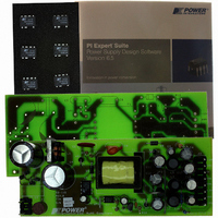
KIT REFERENCE DESIGN W/TN376PN
Manufacturer
Power Integrations
Series
TinySwitch®-PKr
Specifications of RDK-115
Main Purpose
AC/DC, Primary Side
Outputs And Type
4, Isolated
Power - Output
7.5W
Voltage - Output
3.3V, 5V, 12V, -12V
Current - Output
500mA, 500mA, 250mA, 30mA
Voltage - Input
85 ~ 265VAC
Regulator Topology
Flyback
Frequency - Switching
132kHz
Board Type
Fully Populated
Utilized Ic / Part
TNY376
Product
Accessories & Kits
Lead Free Status / RoHS Status
Not applicable / Not applicable
Other names
596-1145


8 Design Spreadsheet
ACDC_TinySwitch-PK_
041207; Rev.0.22; Copyright
Power Integrations 2007
ENTER APPLICATION VARIABLES
VACMIN
VACMAX
fL
VO
Peak Load Current, IO
Peak Power
Continuous / Average Power
n
Z
tC
CIN
ENTER TinySwitch-PK VARIABLES
TinySwitch-PK
Chosen Device
Chose Configuration
ILIMITMIN
ILIMITTYP
ILIMITMAX
fSmin
I^2fmin
PO_132kHz
VOR
VDS
VD
KP
KP_TRANSIENT
ENTER BIAS WINDING VARIABLES
VB
VDB
NB
VZOV
UVLO VARIABLES
V_UV_TARGET
V_UV_ACTUAL
RUV_IDEAL
RUV_ACTUAL
ENTER TRANSFORMER CORE/CONSTRUCTION VARIABLES
Core Type
Power Integrations
Tel: +1 408 414 9200 Fax: +1 408 414 9201
www.powerint.com
TNY376
INPUT
135.00
EEL19
44.00
2.60
0.67
5.00
3.00
265
INC
7.5
85
50
TNY376
INFO
Increase
TNY376
OUTPU
Current
248000
100.07
914.70
EEL19
13.00
0.465
0.500
0.535
59.40
22.00
12.00
28.00
36.50
Limit
8.77
0.53
0.36
0.70
3.91
135
7.5
0.6
0.5
44
10
T
d
mSecon
uFarads Input Capacitance
A^2kHz I^2f (product of current limit squared and frequency is
Mohms Calculated value for UV Lockout resistor
Mohms Closest standard value of resistor to RUV_IDEAL
Amps
Watts
Watts
Amps
Amps
Amps
Watts
UNIT
Hertz
Hertz
Volts
Volts
Volts
Volts
Volts
Volts
Volts
Volts
Volts
Volts
Volts
ds
ACDC_TinySwitch-PK_041207_Rev0-22.xls;
TinySwitch-PK Continuous/Discontinuous
Flyback Transformer Design Spreadsheet
Minimum AC Input Voltage
Maximum AC Input Voltage
AC Mains Frequency
Output Voltage (at continuous power)
Power Supply Output Current (corresponding to peak power)
Peak Output Power. Used in estimation of Primary
inductance
Continuous/Average Output Power. Used in estimation of
Core size
Efficiency Estimate at output terminals. Under 0.7 if no better
data available
Z Factor. Ratio of secondary side losses to the total losses in
the power supply. Use 0.6 if no better data available
Bridge Rectifier Conduction Time Estimate
User defined TinySwitch-PK
Enter "RED" for reduced current limit (sealed adapters),
"STD" for standard current limit or "INC" for increased current
limit (peak or higher power applications)
Minimum Current Limit
Maximum Current Limit
Minimum Device Switching Frequency
trimmed for tighter tolerance)
Estimated Maximum Power while still in 132 kHz operation
Reflected Output Voltage (VOR < 135 V Recommended)
TinySwitch-PK on-state Drain to Source Voltage
Output Winding Diode Forward Voltage Drop
Ripple to Peak Current Ratio (KP < 6)
Transient Ripple to Peak Current Ratio. Ensure
KP_TRANSIENT > 0.25
Bias Winding Voltage
Bias Winding Number of Turns
Over Voltage Protection zener diode.
Target under-voltage threshold, above which the power
supply will start
Typical start-up voltage based on standard value of
RUV_ACTUAL
User defined Core Size (Verify thermal performance under
Page 16 of 36
Related parts for RDK-115
Image
Part Number
Description
Manufacturer
Datasheet
Request
R

Part Number:
Description:
KIT REF DESIGN FOR LNK457D
Manufacturer:
Power Integrations
Datasheet:

Part Number:
Description:
REFERENCE DESIGN LINKSWITCH-PH
Manufacturer:
Power Integrations
Datasheet:

Part Number:
Description:
KIT REF DESIGN FOR LNK403EG
Manufacturer:
Power Integrations
Datasheet:

Part Number:
Description:
KIT REF DESIGN FOR LNK406EG
Manufacturer:
Power Integrations
Datasheet:

Part Number:
Description:
KIT REF DESIGN LINKSWITCH-CV
Manufacturer:
Power Integrations
Datasheet:

Part Number:
Description:
KIT REF DESIGN LINKSWITCH 2
Manufacturer:
Power Integrations
Datasheet:

Part Number:
Description:
Specifications: Family: Eval Boards - DC/DC & AC/DC (Off-Line) SMPS ; Series: HiperLCS™ ; Main Purpose: DC/DC, Step Down ; Outputs and Type: 1, Isolated ; Power - Output: 150W ; Voltage - Output: 24V ; Current - Output: 6.25A ; Voltage - Input:
Manufacturer:
Power Integrations, Inc.
Datasheet:

Part Number:
Description:
KIT DESIGN REF TINYSWITCH-III
Manufacturer:
Power Integrations
Datasheet:

Part Number:
Description:
KIT DESIGN REF LINKSWITCH LP
Manufacturer:
Power Integrations
Datasheet:

Part Number:
Description:
KIT REF DESIGN LED LINKSWITCH TN
Manufacturer:
Power Integrations
Datasheet:
Part Number:
Description:
KIT REF DESIGN PG LINKSWITCH-II
Manufacturer:
Power Integrations
Datasheet:
Part Number:
Description:
REFERENCE DESIGN LINKSWITCH-PL
Manufacturer:
Power Integrations
Datasheet:
Part Number:
Description:
REFERENCE DESIGN LINKSWITCH-PH
Manufacturer:
Power Integrations
Datasheet:

Part Number:
Description:
KIT REF DESIGN 36-72W MOTOR DRVR
Manufacturer:
Power Integrations
Datasheet:
Part Number:
Description:
Specifications: Manufacturer: Power Integrations ; Output Voltage: 380 VDC ; Input / Supply Voltage (Max): 264 VAC ; Input / Supply Voltage (Min): 90 VAC ; Mounting Style: Through Hole ; Output Current: 0.913 A ; Output Power: 347 W
Manufacturer:
Power Integrations, Inc.