STEVAL-ISA019V2 STMicroelectronics, STEVAL-ISA019V2 Datasheet - Page 17
STEVAL-ISA019V2
Manufacturer Part Number
STEVAL-ISA019V2
Description
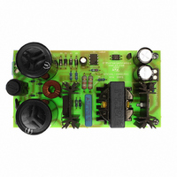
BOARD EVAL SMPS L6565 3PHASE APP
Manufacturer
STMicroelectronics
Type
Motor / Motion Controllers & Driversr
Specifications of STEVAL-ISA019V2
Mfg Application Notes
L6565/STC04IE170HV AppNote
Main Purpose
AC/DC, Primary Side
Outputs And Type
1, Isolated
Power - Output
80W
Voltage - Output
24V
Current - Output
3.33A
Voltage - Input
250 ~ 850V
Regulator Topology
Flyback
Board Type
Fully Populated
Utilized Ic / Part
L6565, STC04IE170HV
Input Voltage
250 V to 850 V
Output Voltage
24 V
Product
Power Management Modules
Lead Free Status / RoHS Status
Lead free / RoHS Compliant
Frequency - Switching
-
Lead Free Status / Rohs Status
Lead free / RoHS Compliant
For Use With/related Products
L6565, STC04IE170HV
Other names
497-6339


AN2495
5
Startup network design
To allow the circuit to start as soon as the line voltage is applied, it is necessary to pre-
charge both C
A resistor connected to the DC bus directly makes the pre-charge of C
capacitance. The circuit must start at a minimum DC input voltage of 250 V. The current
required by the L6565 driver during the startup time determines the (R
Considering that the L6565 driver needs a 0.07 mA maximum startup current, we obtain:
Equation 33
Startup resistance must be lower than 3.6 MΩ to reach the best trade-off between power
dissipation and time-to-start. As a consequence, before choosing the startup resistor, we
must determine the C
must be able to supply the L6565 driver until the steady state behavior of the converter is
established. The time from bench verification is 20 ms maximum. Given a L6565 minimum
hysteresis-voltage (difference between startup threshold and undervoltage threshold) of 3.7
V, the voltage across C5 must decrease less than 3.7 V during the startup period. From the
L6565 datasheet we know that maximum quiescent current after turn-on is 3.5 mA, so C5
must be chosen such that:
Equation 34
C
Finally, we can set the startup resistance value to reduce time-to-start and simultaneously
optimize standby power dissipation. The L6565 has a maximum startup threshold of 14.5 V,
therefore the maximum time-to-start is approximately:
Equation 35
A good choice is to put in series four 200 kΩ resistors (R
dissipate less than 1 W of standby power.
The pre-charge of C
L6565 through a diode in series with a 2.2 kΩ resistor.
5
=33 µF is a good choice to guarantee a good margin.
Time - to - start
5
and C
=
8
5
-------------------------------------------------------------------------
⎛
⎝
8
base capacitance is carries out by connecting it to the OUT pin of the
--------------------------------------------------- -
(
capacitance value, which is set according to another requirement. C
ΔV
R
capacitances.
(
1
R
+
1
=
+
R
V
I
----------------
C
2
R
Q
inmin
Doc ID 13127 Rev 4
C
5
+
2
•
5
•
+
R
Δt
14.5V
3
R
<
+
3
3.7V
+
R
4
R
)
4
⎞
⎠
)
⇒
–
<
I
V
----------------
C
SU
inmin
I
5
SU
>
≤
3.5mA 20ms
-------------------------------------- -
2
=
sec
-------------------- -
0.07mA
3.7V
250V
⇒
•
1
= R
(
R
1
≅
2
+
3.6MΩ
= R
≅
R
19μF
2
3
+
Startup network design
= R
R
1
3
+ R
5
4
+
= 200 kΩ), which
electrolytic
R
2
4
+ R
)
≤
808kΩ
3
+ R
4
) value.
17/34
5
Related parts for STEVAL-ISA019V2
Image
Part Number
Description
Manufacturer
Datasheet
Request
R

Part Number:
Description:
BOARD RGB CTR ST7,STP08C596MTR
Manufacturer:
STMicroelectronics
Datasheet:

Part Number:
Description:
Power Management IC Development Tools Full Speed USB to RS232 Bridge Demo
Manufacturer:
STMicroelectronics
Datasheet:
Part Number:
Description:
Power Management IC Development Tools 2.5W solar eval BRD USB SPV1040 LD39050
Manufacturer:
STMicroelectronics
Datasheet:

Part Number:
Description:
BOARD EVAL FOR MEMS SENSORS
Manufacturer:
STMicroelectronics
Datasheet:

Part Number:
Description:
KIT DEV STARTER ST10F276Z5
Manufacturer:
STMicroelectronics
Datasheet:

Part Number:
Description:
BOARD EVAL HDMI $ VIDEO SWITCH
Manufacturer:
STMicroelectronics
Datasheet:

Part Number:
Description:
BOARD DEMO ACCELEROMETER DIL24
Manufacturer:
STMicroelectronics
Datasheet:

Part Number:
Description:
BOARD STLM75/STDS75/ST72F651
Manufacturer:
STMicroelectronics
Datasheet:

Part Number:
Description:
EVAL BOARD 3AXIS MEMS ACCELLRMTR
Manufacturer:
STMicroelectronics
Datasheet:

Part Number:
Description:
BOARD EVAL 8BIT MICRO + TDE1708
Manufacturer:
STMicroelectronics
Datasheet:
Part Number:
Description:
STMicroelectronics [RIPPLE-CARRY BINARY COUNTER/DIVIDERS]
Manufacturer:
STMicroelectronics
Datasheet:
Part Number:
Description:
STMicroelectronics [LIQUID-CRYSTAL DISPLAY DRIVERS]
Manufacturer:
STMicroelectronics
Datasheet:
Part Number:
Description:
BOARD EVAL FOR MEMS SENSORS
Manufacturer:
STMicroelectronics
Datasheet: