STEVAL-ISA019V2 STMicroelectronics, STEVAL-ISA019V2 Datasheet - Page 19
STEVAL-ISA019V2
Manufacturer Part Number
STEVAL-ISA019V2
Description
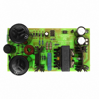
BOARD EVAL SMPS L6565 3PHASE APP
Manufacturer
STMicroelectronics
Type
Motor / Motion Controllers & Driversr
Specifications of STEVAL-ISA019V2
Mfg Application Notes
L6565/STC04IE170HV AppNote
Main Purpose
AC/DC, Primary Side
Outputs And Type
1, Isolated
Power - Output
80W
Voltage - Output
24V
Current - Output
3.33A
Voltage - Input
250 ~ 850V
Regulator Topology
Flyback
Board Type
Fully Populated
Utilized Ic / Part
L6565, STC04IE170HV
Input Voltage
250 V to 850 V
Output Voltage
24 V
Product
Power Management Modules
Lead Free Status / RoHS Status
Lead free / RoHS Compliant
Frequency - Switching
-
Lead Free Status / Rohs Status
Lead free / RoHS Compliant
For Use With/related Products
L6565, STC04IE170HV
Other names
497-6339


AN2495
Figure 9.
Its transfer function, which comprises a pole at the origin and a zero-pole pair, is given by:
Equation 38
The task of the control loop design is then to determine the transfer function G
that the resulting closed-loop system is stable and performs well in terms of dynamic
response, and line and load regulation. It is well known that the characteristics of the closed-
loop system can be inferred from its open loop transfer function properties, that is G(s) =
G
Frequency response requirements are summarized below:
1.
2.
3.
First choose a typical value for R
From the L6565 datasheet we know that I
and can obtain:
Equation 39
R
parallel to the photodiode.
24
1
(s) · G
= 1.5 kΩ is a good choice. It is good practice to put a 3.3 kΩ resistor (R
Optimum dynamic performance requires a large gain bandwidth, that is the open-loop
cross-over frequency f
Phase margin ϕ
ensures fast transient response with very little ringing. Sometimes this is not enough
and so phase shift should be lower than 180° at any frequency below f
phase shift over 180° would result in a conditionally stable system.
Good load and line regulation implies a high DC gain (this requirement is ensured by
the feedback network, whose transfer function has a pole at the origin).
2
(s).
Converter feedback network
G
2
s ( )
R
m
B
comprised between 45° and 90° is used as a design guideline. This
=
=
v
-----------------------
R
V
comp
24
C
out
to be typically chosen equal to f
<
s ( )
Doc ID 13127 Rev 4
s ( )
V
-------------------------------------------------------
out
L
=
= R
–
CTR
----------------------------------------------- -
(
22
V
I
comp
ref
= 2.7 kΩ.
R
max
comp
B
–
R
V
Frequency response and loop compensation
•
H
diode
R
C
= 5 mA (source current) and R
COMP
F
)
=
24V 3.5V
---------------------------- -
•
1
-- -
s
5mA
•
–
------------------------------------------------- -
1
1
+
+
sw
sR
s R
(
=
/5 (f
COMP
4.1kΩ
H
+
c
R
= 10 kHz).
C
F
comp
)C
F
23
C
, because a
comp
= 3.3 kΩ) in
2
(s) to ensure
= 15 kΩ.
19/34
Related parts for STEVAL-ISA019V2
Image
Part Number
Description
Manufacturer
Datasheet
Request
R

Part Number:
Description:
BOARD RGB CTR ST7,STP08C596MTR
Manufacturer:
STMicroelectronics
Datasheet:

Part Number:
Description:
Power Management IC Development Tools Full Speed USB to RS232 Bridge Demo
Manufacturer:
STMicroelectronics
Datasheet:
Part Number:
Description:
Power Management IC Development Tools 2.5W solar eval BRD USB SPV1040 LD39050
Manufacturer:
STMicroelectronics
Datasheet:

Part Number:
Description:
BOARD EVAL FOR MEMS SENSORS
Manufacturer:
STMicroelectronics
Datasheet:

Part Number:
Description:
KIT DEV STARTER ST10F276Z5
Manufacturer:
STMicroelectronics
Datasheet:

Part Number:
Description:
BOARD EVAL HDMI $ VIDEO SWITCH
Manufacturer:
STMicroelectronics
Datasheet:

Part Number:
Description:
BOARD DEMO ACCELEROMETER DIL24
Manufacturer:
STMicroelectronics
Datasheet:

Part Number:
Description:
BOARD STLM75/STDS75/ST72F651
Manufacturer:
STMicroelectronics
Datasheet:

Part Number:
Description:
EVAL BOARD 3AXIS MEMS ACCELLRMTR
Manufacturer:
STMicroelectronics
Datasheet:

Part Number:
Description:
BOARD EVAL 8BIT MICRO + TDE1708
Manufacturer:
STMicroelectronics
Datasheet:
Part Number:
Description:
STMicroelectronics [RIPPLE-CARRY BINARY COUNTER/DIVIDERS]
Manufacturer:
STMicroelectronics
Datasheet:
Part Number:
Description:
STMicroelectronics [LIQUID-CRYSTAL DISPLAY DRIVERS]
Manufacturer:
STMicroelectronics
Datasheet:
Part Number:
Description:
BOARD EVAL FOR MEMS SENSORS
Manufacturer:
STMicroelectronics
Datasheet: