MULTIPHSPOL-RD Silicon Laboratories Inc, MULTIPHSPOL-RD Datasheet - Page 5
MULTIPHSPOL-RD
Manufacturer Part Number
MULTIPHSPOL-RD
Description
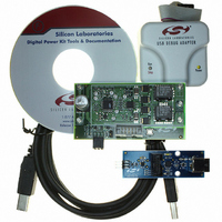
KIT REFERENCE DESIGN FOR SI825X
Manufacturer
Silicon Laboratories Inc
Type
Other Power Managementr
Specifications of MULTIPHSPOL-RD
Main Purpose
DC/DC, Step Down
Outputs And Type
1, Non-Isolated
Voltage - Output
3.3V
Current - Output
40A
Voltage - Input
10 ~ 15V
Regulator Topology
Buck
Frequency - Switching
391kHz
Board Type
Fully Populated
Utilized Ic / Part
SI8250, SI8251, SI8252
Input Voltage
10 V to 15 V
Output Voltage
3.3 V
Interface Type
USB
Product
Power Management Modules
Supply Current
10 A
For Use With/related Products
Si8250
Lead Free Status / RoHS Status
Contains lead / RoHS non-compliant
Power - Output
-
Lead Free Status / Rohs Status
Lead free / RoHS Compliant
Other names
336-1323


5. Development/Debug Operation: Software Setup
The Si825x Multi-Phase POL Reference Design comes with Application Builder software (detailed in "8. Si825x
Application Builder” on page 12), a configurable real-time software Kernel, and a software Kernel compiled
specifically for the Si8250 Multi-Phase POL Target Board.
The Kernel is royalty-free application software for the Si825x family of digital power controllers that greatly reduces
application program development time, effort, and engineering risk. The Application Builder is used to customize
the Kernel and create C-code source level application software for the Si825x end application. The Application
Builder directly modifies the source code in the Kernel, which is then compiled and downloaded to the Si825x. For
more information on the Kernel, see application note “AN271: Si8250 Real-Time Kernel Overview”.
The Multi_Phase_POL directory (SiLabs\Power\Reference_Designs\Multi_Phase_POL\Firmware) contains the
Kernel configured for the Si8250 Multi-Phase POL Target Board.
Kernel software can be loaded/reloaded to the target board using the Silicon Laboratories IDE. Note that hardware
must be set up as detailed in "4. Development/Debug Operation: Initial Hardware Setup” on page 4. Follow the
instructions below to configure and download the Multi_Phase_POL application software for the Si8250 Multi-
Phase POL Target Board.
Note: A thorough understanding of the IDE is required before one can use the development/Debug Mode of the kit. The IDE is
1. The included CD-ROM contains the Silicon Laboratories Integrated Development Environment (IDE),
2. Open the IDE by selecting Silicon Laboratories→Silicon Laboratories IDE from the PC programs menu.
3. Next, the example project included with the kit is opened. Select Project→Open Project... from the IDE
4. The Si8250 Multi-Phase POL Target Board has several connection requirements that must be specified before
5. Click the Connect button in the toolbar or select Debug→Connect from the menu to connect to the device.
6. Build the project by clicking on the Build/Make Project button in the toolbar or by selecting Project→Build/
Application Builder examples, the PMBus Monitor, Keil software 8051 tools, and additional documentation.
Insert the CD-ROM into your PC’s CD-ROM drive. An installer will automatically launch allowing you to install
the software or read documentation by clicking buttons on the installation panel. If the installer does not
automatically start when you insert the CD-ROM, run autorun.exe found in the root directory of the CD-ROM.
Refer to the ReleaseNotes.txt file on the CD-ROM for the latest information regarding known problems and
restrictions. See "7. Silicon Laboratories Integrated Development Environment” on page 9 for further
information on the development tools.
menus. In the Project Workspace window, browse to the
“SiLabs\Power\Reference_Designs\Multi_Phase_POL\Firmware\Multi_phase_POL\Source” directory and
select the *.wsp project file. Press Open to close the window and open the project.
Note: This example will only work with the full version of the Keil compiler. If the demonstration compiler is used, use the
connecting to the board. Select Options→Connection Options... from the IDE menu. In the Connection
Options window, select USB Debug Adapter in the Serial Adapter section. Next, select C2 in the Debug
Interface section. The Si825x family of devices use the Silicon Laboratories 2-wire (C2) debug interface. Click
OK to close the window.
Make Project from the menu.
Note: After the project has been built the first time, the Build/Make Project command will only build the files that have
detailed in "7. Silicon Laboratories Integrated Development Environment".
files in “SiLabs\Power\Reference_Designs\Multi_Phase_POL\Firmware\Multi_phase_POL_basic\Source”. This
code will compile to less than 4 kB of code.
been changed since the previous build. To rebuild all files and project dependencies, click on the Rebuild All button
in the toolbar or select Project→Rebuild All from the menu.
Confidential Rev. 0.2
Si825x Multi-Phase POL-RD
5
Related parts for MULTIPHSPOL-RD
Image
Part Number
Description
Manufacturer
Datasheet
Request
R

Part Number:
Description:
SMD/C°/SINGLE-ENDED OUTPUT SILICON OSCILLATOR
Manufacturer:
Silicon Laboratories Inc
Part Number:
Description:
Manufacturer:
Silicon Laboratories Inc
Datasheet:
Part Number:
Description:
N/A N/A/SI4010 AES KEYFOB DEMO WITH LCD RX
Manufacturer:
Silicon Laboratories Inc
Datasheet:
Part Number:
Description:
N/A N/A/SI4010 SIMPLIFIED KEY FOB DEMO WITH LED RX
Manufacturer:
Silicon Laboratories Inc
Datasheet:
Part Number:
Description:
N/A/-40 TO 85 OC/EZLINK MODULE; F930/4432 HIGH BAND (REV E/B1)
Manufacturer:
Silicon Laboratories Inc
Part Number:
Description:
EZLink Module; F930/4432 Low Band (rev e/B1)
Manufacturer:
Silicon Laboratories Inc
Part Number:
Description:
I°/4460 10 DBM RADIO TEST CARD 434 MHZ
Manufacturer:
Silicon Laboratories Inc
Part Number:
Description:
I°/4461 14 DBM RADIO TEST CARD 868 MHZ
Manufacturer:
Silicon Laboratories Inc
Part Number:
Description:
I°/4463 20 DBM RFSWITCH RADIO TEST CARD 460 MHZ
Manufacturer:
Silicon Laboratories Inc
Part Number:
Description:
I°/4463 20 DBM RADIO TEST CARD 868 MHZ
Manufacturer:
Silicon Laboratories Inc
Part Number:
Description:
I°/4463 27 DBM RADIO TEST CARD 868 MHZ
Manufacturer:
Silicon Laboratories Inc
Part Number:
Description:
I°/4463 SKYWORKS 30 DBM RADIO TEST CARD 915 MHZ
Manufacturer:
Silicon Laboratories Inc
Part Number:
Description:
N/A N/A/-40 TO 85 OC/4463 RFMD 30 DBM RADIO TEST CARD 915 MHZ
Manufacturer:
Silicon Laboratories Inc
Part Number:
Description:
I°/4463 20 DBM RADIO TEST CARD 169 MHZ
Manufacturer:
Silicon Laboratories Inc