MULTIPHSPOL-RD Silicon Laboratories Inc, MULTIPHSPOL-RD Datasheet - Page 7
MULTIPHSPOL-RD
Manufacturer Part Number
MULTIPHSPOL-RD
Description
KIT REFERENCE DESIGN FOR SI825X
Manufacturer
Silicon Laboratories Inc
Type
Other Power Managementr
Specifications of MULTIPHSPOL-RD
Main Purpose
DC/DC, Step Down
Outputs And Type
1, Non-Isolated
Voltage - Output
3.3V
Current - Output
40A
Voltage - Input
10 ~ 15V
Regulator Topology
Buck
Frequency - Switching
391kHz
Board Type
Fully Populated
Utilized Ic / Part
SI8250, SI8251, SI8252
Input Voltage
10 V to 15 V
Output Voltage
3.3 V
Interface Type
USB
Product
Power Management Modules
Supply Current
10 A
For Use With/related Products
Si8250
Lead Free Status / RoHS Status
Contains lead / RoHS non-compliant
Power - Output
-
Lead Free Status / Rohs Status
Lead free / RoHS Compliant
Other names
336-1323


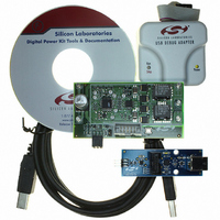
6. PMBus Operation
PMBus is a connectivity solution designed for networking multiple power supplies using a single management bus.
The Real-time Kernel provided with the Si825x Multi-Phase POL Reference Design includes optional support for
PMBus. In addition, the Si825x POL design kit also comes with a PMBus Monitor application and USB to SMBus
Bridge Board to manage the power supply through PMBus.
1. The PMBus Monitor software is installed during the initial software setup. (See "5. Development/Debug
2. Connect the board as shown in "3. Si8250 Multi Phase POL Target Board Stand-Alone Operation” on page 3.
3. Drivers must be installed to allow the PMBus Monitor to communicate with the USB to SMBus Bridge Board.
4. Connect the USB to SMBus Bridge Board to an available USB slot on your PC with a USB cable.
5. Windows will open a Found New Hardware Wizard window. Press Next after selecting the (Recommended)
6. Connect the Si8250 Multi-Phase POL Target Board to the USB to SMBus Bridge Board as shown in Figure 4.
Operation: Software Setup” on page 5.)
Note that the PMBus Monitor may also be operated with the USB Debug Adaptor. If this is desired, connect the
target board as shown in "4. Development/Debug Operation: Initial Hardware Setup” on page 4.
The driver files are located by default in the "Silabs\Power\Si825x AppBuilder\PMBus Monitor\USB-SMBus
Bridge Board Drivers" directory. Run the PreInstaller.exe application. This program will copy the driver files to
the PC's "Program Files" directory and then register the driver files so the board will be recognized when it is
connected. Windows Logo testing warnings may appear. Press the Continue Anyway button.
option. Windows Logo testing warnings may appear. Press the Continue Anyway button. Press "Finish" to
finish installing the USB to SMBus Bridge Board.
Figure 4. USB to SMBus Bridge Board Connection (Load not Connected)
Confidential Rev. 0.2
Si825x Multi-Phase POL-RD
7
Related parts for MULTIPHSPOL-RD
Image
Part Number
Description
Manufacturer
Datasheet
Request
R

Part Number:
Description:
SMD/C°/SINGLE-ENDED OUTPUT SILICON OSCILLATOR
Manufacturer:
Silicon Laboratories Inc
Part Number:
Description:
Manufacturer:
Silicon Laboratories Inc
Datasheet:
Part Number:
Description:
N/A N/A/SI4010 AES KEYFOB DEMO WITH LCD RX
Manufacturer:
Silicon Laboratories Inc
Datasheet:
Part Number:
Description:
N/A N/A/SI4010 SIMPLIFIED KEY FOB DEMO WITH LED RX
Manufacturer:
Silicon Laboratories Inc
Datasheet:
Part Number:
Description:
N/A/-40 TO 85 OC/EZLINK MODULE; F930/4432 HIGH BAND (REV E/B1)
Manufacturer:
Silicon Laboratories Inc
Part Number:
Description:
EZLink Module; F930/4432 Low Band (rev e/B1)
Manufacturer:
Silicon Laboratories Inc
Part Number:
Description:
I°/4460 10 DBM RADIO TEST CARD 434 MHZ
Manufacturer:
Silicon Laboratories Inc
Part Number:
Description:
I°/4461 14 DBM RADIO TEST CARD 868 MHZ
Manufacturer:
Silicon Laboratories Inc
Part Number:
Description:
I°/4463 20 DBM RFSWITCH RADIO TEST CARD 460 MHZ
Manufacturer:
Silicon Laboratories Inc
Part Number:
Description:
I°/4463 20 DBM RADIO TEST CARD 868 MHZ
Manufacturer:
Silicon Laboratories Inc
Part Number:
Description:
I°/4463 27 DBM RADIO TEST CARD 868 MHZ
Manufacturer:
Silicon Laboratories Inc
Part Number:
Description:
I°/4463 SKYWORKS 30 DBM RADIO TEST CARD 915 MHZ
Manufacturer:
Silicon Laboratories Inc
Part Number:
Description:
N/A N/A/-40 TO 85 OC/4463 RFMD 30 DBM RADIO TEST CARD 915 MHZ
Manufacturer:
Silicon Laboratories Inc
Part Number:
Description:
I°/4463 20 DBM RADIO TEST CARD 169 MHZ
Manufacturer:
Silicon Laboratories Inc