NCP1203GEVB ON Semiconductor, NCP1203GEVB Datasheet
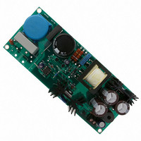
EVAL BOARD FOR NCP1203G

NCP1203GEVB

Manufacturer Part Number
NCP1203GEVB
Description
EVAL BOARD FOR NCP1203G
Manufacturer
ON Semiconductor
Datasheets

Specifications of NCP1203GEVB

Design Resources
NCP1203GEVB BOM NCP1203GEVB Gerber Files NCP1203 EVB Schematic
Main Purpose
AC/DC, Primary Side
Outputs And Type
1, Isolated
Voltage - Output
19V
Current - Output
4A
Voltage - Input
85 ~ 230VAC
Regulator Topology
Flyback
Frequency - Switching
60kHz
Board Type
Fully Populated
Utilized Ic / Part
NPC1200
Lead Free Status / RoHS Status
Lead free / RoHS Compliant
Power - Output
-
Lead Free Status / Rohs Status
Lead free / RoHS Compliant
For Use With/related Products
NCP1203G
Other names
NCP1203GEVBOS
AND8076/D
A 70 W Low Standby
Power Supply with
the NCP120x Series
Prepared by: Christophe Basso
ON Semiconductor
build efficient and cost-effective Switch-Mode Power
Supplies (SMPS). As this design example will show, the part
definition does not confine the component in low-power
applications only, but it can actually be used in Flyback and
Forward supplies for virtually any output power. The below
example depicts a universal mains 90-260 VAC power
supply delivering 16.5 V @ 4.5 A.
true low standby power designs. This application note
details how an amazing standby power of less than 100 mW
can be reached at high line with a nominal 70 W board.
DSS or Not DSS?
MOSFETs from the high-voltage rail. This option brings
you several advantages, as stated below:
April, 2003 - Rev. 2
The NCP1200 represents one of the cheapest solutions to
Beside its ease of implementation, the NCP1200 excels in
The Dynamic Self Supply (DSS) lets you directly drive
True overload detection: with UC384X-based systems,
the switching oscillations are stopped in case the Vcc
line drops below a given Undervoltage Lockout level
(UVLO). This principle considers a good coupling
between the primary auxiliary winding and the power
secondary winding. Unfortunately, leakage elements
often degrade this coupling and you only can detect true
short-circuit (when Vout is close to zero) and not
overload conditions. Thanks to the DSS, the NCP1200
does not need an auxiliary information to sense an
overload condition. By detecting a current setpoint
pushed to the maximum, the internal logic takes the
decision to enter into a safe burst operation,
auto-recovering when the default leaves. Precise
overload levels can thus be implemented.
Guaranteed operation at low output levels: the Vcc
delivered by an auxiliary winding moves with the
power output level because a coupling exists between
both windings. When the supply is used in battery
charging applications, Vout can move depending on the
charging state. That is to say, when the battery is nearly
empty, its voltage can be close to zero, forcing Vout at
Semiconductor Components Industries, LLC, 2003
INTRODUCTION
1
the other hand, it can sometimes compromise key design
parameters. Standby power and power dissipation are one of
these:
If you would like to have a precise Over Current Protection
(OCP) trip point while driving a moderate size MOSFET,
DSS can be a good choice, provided low standby power is
not an absolute necessity. In our case, we want to drive a
large MOSFET for a better efficiency but we need to reach
the lowest possible standby power. We will thus adopt an
auxiliary winding configuration to permanently disable the
DSS. Solutions to various combinations of these constraints
are described in the application note “Tips and Tricks for the
NCP1200,” document number AND8069/D.
As you can see, the DSS offers interesting features but, on
As a result, the answer lies behind your design constraints.
this level. Thanks to the natural secondary / auxiliary
reflection, the primary auxiliary winding cannot
maintain a sufficient voltage on the control IC: Vcc
collapses and puts the controller in trouble, probably
entering an hiccup mode, similar to that of a startup
sequence. DSS being decoupled from Vout, you never
see that phenomenon.
Standby power: the DSS standby power contribution
can easily be evaluated: V
consumption taken by the controller and V
high-voltage supply rail. If I
have a standby power of 350 mW at a 350 VDC voltage
rail. Tricks exist to slightly reduce it, like the half-wave
diode, but you will only gain between 20–30%.
Power dissipation: as stated above, all the current
consumed by the IC is seen through pin8. This is due to
the self-adaptive feature of the DSS. Should the IC
current move up or down, the DSS duty-cycle will
automatically adjust to deliver it. The controller current
depends on the internal IC consumption, but also on the
type of MOSFET connected to the output. It therefore
important to assess the total current drawn from the HV
rail and checks the right compatibility with the package
type. All details are given in the NCP1200 dedicated
data sheet and the application note AND8023/D.
APPLICATION NOTE
http://onsemi.com
HV
avg
I
Publication Order Number:
avg
equals 1 mA, then we
with I
avg
HV
, the current
AND8076/D
, the

Related parts for NCP1203GEVB

NCP1203GEVB Summary of contents

Page 1

... AND8076 Low Standby Power Supply with the NCP120x Series Prepared by: Christophe Basso ON Semiconductor INTRODUCTION The NCP1200 represents one of the cheapest solutions to build efficient and cost-effective Switch-Mode Power Supplies (SMPS). As this design example will show, the part definition does not confine the component in low-power applications only, but it can actually be used in Flyback and Forward supplies for virtually any output power ...

Page 2

Self-Powering the Controller in Standby An auxiliary winding does not usually cause any self-supply problem with a continuous pulses flow. In standby, whatever implemented frequency reduction techniques (e.g. skip or frequency foldback), the recurrence between pulses can become very low. ...

Page 3

Pin Pout Iload + + Vrect avg h @ Vpeak * [ 860 VAC input voltage Thanks to Figure 3 information, we can evaluate ...

Page 4

... As a result, you re-start with new values and see if they finally fit your needs. To help you speed-up the transformer design, a design-aid spreadsheet is available from the ON Semiconductor web site, www.onsemi.com/pub/NCP1200. Let’s start the process with the turn ratio calculation. ...

Page 5

DRV Radd1 sense C Radd2 150 Figure 6. A Very Simple Way to Generate a Ramp from a Square Wave Signal From the Flyback formula, we obtain Pout ...

Page 6

Vcc + Vdrv @ with t = 0.45 1/61 k. This provides an available ramp level of 677 mV/ s (S). By ...

Page 7

Idrain Iprim 3.00 2.00 1.00 0 -1.00 2.40 2.00 1.60 1.20 800 M 10.00 6.00 2.00 -2.00 -6.00 156 154 152 150 148 2.01 M Figure 9. Complete Simulation Results of the 70 W Converter Operated at ...

Page 8

Transformer Below are the key parameters you will pass to your transformer manufacturer to help him select the right winding size and tailor the internal gap: Maximum peak primary current, including 160 ns propagation delay 0.33 + 374 ...

Page 9

NCP1200 averaged IN OUT CTRL FB GND 2.93 Vin 340 11 12 LoL 1 1 CoL Vin 1.0 kF 350 0 14 VStim + SFH610A 2.93 Vout 15 C5 1.0 nF Figure 10. The Simulation ...

Page 10

Figure 13. The Simulation Schematic for Our 70 W Current-Mode Power Supply http://onsemi.com AND8076/D Input Universal 10 ...

Page 11

Input Voltage (VAC) Figure 14. Line Regulation Is Excellent Thanks to Current Mode and a Good Open-Loop DC Gain Board Final Results Standby Power Measured on ...

Page 12

... Q2 2N2222 - L1 PCV-2-103-05 Philips 2222-157-46221 L2 B82724-A2142- Philips M1 2SK2543 (Toshiba) or 2222-136-50222 FQP6N60 (Fairchild) Philips T1 Z9260-A or Z9007-B 2222-136-50222 Heatsink 1 KL194/38,1 SW (diode) Philips Heatsink 2 KL195/38,1 SW (MOSFET) 2222-136-50222 - http://onsemi.com General Semi ON Semiconductor - - - ON Semiconductor - ON Semiconductor - Infineon ON Semiconductor ON Semiconductor ON Semiconductor ON Semiconductor Coilcraft EPCOS Coilcraft Seifert Seifert ...

Page 13

Appendix B, Transformer Manufacturers Eldor Corporation Headquarter Via Plinio 10, 22030 Orsenigo (Como) Italia Tel. : +39-031-636 111 Fax : +39-031 636 280 eldor@eldor.it www.eldor.it ref. : 2074.5059A, no aux. winding Pulse Engineering Site d’Orgelet Zone ...

Page 14

... Fax: 303-675-2176 or 800-344-3867 Toll Free USA/Canada Email: ONlit@hibbertco.com N. American Technical Support: 800-282-9855 Toll Free USA/Canada AND8076/D JAPAN: ON Semiconductor, Japan Customer Focus Center 2-9-1 Kamimeguro, Meguro-ku, Tokyo, Japan 153-0051 Phone: 81-3-5773-3850 ON Semiconductor Website: http://onsemi.com For additional information, please contact your local Sales Representative ...

Related keywords