NCP1203GEVB ON Semiconductor, NCP1203GEVB Datasheet - Page 11
NCP1203GEVB
Manufacturer Part Number
NCP1203GEVB
Description
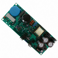
EVAL BOARD FOR NCP1203G
Manufacturer
ON Semiconductor
Specifications of NCP1203GEVB
Design Resources
NCP1203GEVB BOM NCP1203GEVB Gerber Files NCP1203 EVB Schematic
Main Purpose
AC/DC, Primary Side
Outputs And Type
1, Isolated
Voltage - Output
19V
Current - Output
4A
Voltage - Input
85 ~ 230VAC
Regulator Topology
Flyback
Frequency - Switching
60kHz
Board Type
Fully Populated
Utilized Ic / Part
NPC1200
Lead Free Status / RoHS Status
Lead free / RoHS Compliant
Power - Output
-
Lead Free Status / Rohs Status
Lead free / RoHS Compliant
For Use With/related Products
NCP1203G
Other names
NCP1203GEVBOS


Board Final Results
Standby Power
Watt-hour accumulation mode for best accuracy (run length
= 30 minutes).
Line Regulation
input voltage is moving between both range ends. As one
can see, current mode control with good open- loop gain
ensures a
variation (-106 dB DC audio susceptibility).
Load Regulation
possible to plot the load regulation of the board as shown in
Figure 15.
Measured on an Infratek watt-meter operated in
Vin = 120 VAC, Vout = 16.76 V, Iout = 0
Vin = 240 VAC, Vout = 16.76 V, Iout = 0
The array in Figure 14 shows the performance when the
By varying the load current between 11 W and 70 W, it is
16.740
16.735
16.730
16.725
16.720
16.715
16.710
16.705
16.700
Figure 14. Line Regulation Is Excellent Thanks to
Current Mode and a Good Open-Loop DC Gain
100
Vout less than 1 mV for a 212 VDC input
120
140
Input Voltage (VAC)
160
180
200
Pin = 78 mW
Pin = 84 mW
220
http://onsemi.com
240
AND8076/D
11
Efficiency
winding for best standby performance, and another one with
the Dynamic Self-Supply (DSS) left normally working.
Because of the auxiliary winding, it has been necessary to
further clamp the drain voltage in order to improve the
primary overload detection. It is not necessary with the DSS
and therefore the RCD drain clamp network can be less
aggressive, thus slightly improving the efficiency. Board 2
also features a 6 A MOSFET compared to a 3 A MOSFET
on board 1.
16.765
16.760
16.755
16.750
16.745
16.740
16.735
16.730
16.725
16.720
16.715
We have designed two boards, one using the auxiliary
Board 1, aux. winding: Vin = 110 VAC,
Board 2, DSS:
Figure 15. Load Regulation at Two Different
0
110 VAC
20
Input Voltages
Output Power (W)
240 VAC
Vin = 240 VAC,
Vin = 110 VAC,
Vin = 240 VAC,
40
60
= 79%
= 83.4%
= 83.5%
= 84.8%
80
Related parts for NCP1203GEVB
Image
Part Number
Description
Manufacturer
Datasheet
Request
R

Part Number:
Description:
Current Mode Controller Fixed Frequency Operation
Manufacturer:
ON Semiconductor
Datasheet:
Part Number:
Description:
ON Semiconductor [VOLTAGE REGULATOR]
Manufacturer:
ON Semiconductor
Datasheet:
Part Number:
Description:
357-036-542-201 CARDEDGE 36POS DL .156 BLK LOPRO
Manufacturer:
ON Semiconductor
Datasheet:
Part Number:
Description:
357-036-542-201 CARDEDGE 36POS DL .156 BLK LOPRO
Manufacturer:
ON Semiconductor
Datasheet:
Part Number:
Description:
357-036-542-201 CARDEDGE 36POS DL .156 BLK LOPRO
Manufacturer:
ON Semiconductor
Datasheet:
Part Number:
Description:
357-036-542-201 CARDEDGE 36POS DL .156 BLK LOPRO
Manufacturer:
ON Semiconductor
Datasheet:
Part Number:
Description:
357-036-542-201 CARDEDGE 36POS DL .156 BLK LOPRO
Manufacturer:
ON Semiconductor
Datasheet:
Part Number:
Description:
357-036-542-201 CARDEDGE 36POS DL .156 BLK LOPRO
Manufacturer:
ON Semiconductor
Datasheet:
Part Number:
Description:
357-036-542-201 CARDEDGE 36POS DL .156 BLK LOPRO
Manufacturer:
ON Semiconductor
Datasheet:
Part Number:
Description:
357-036-542-201 CARDEDGE 36POS DL .156 BLK LOPRO
Manufacturer:
ON Semiconductor
Datasheet:
Part Number:
Description:
357-036-542-201 CARDEDGE 36POS DL .156 BLK LOPRO
Manufacturer:
ON Semiconductor
Datasheet:
Part Number:
Description:
357-036-542-201 CARDEDGE 36POS DL .156 BLK LOPRO
Manufacturer:
ON Semiconductor
Datasheet:
Part Number:
Description:
Manufacturer:
ON Semiconductor
Datasheet:
Part Number:
Description:
Manufacturer:
ON Semiconductor
Datasheet: