NCP1203GEVB ON Semiconductor, NCP1203GEVB Datasheet - Page 7
NCP1203GEVB
Manufacturer Part Number
NCP1203GEVB
Description
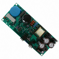
EVAL BOARD FOR NCP1203G
Manufacturer
ON Semiconductor
Specifications of NCP1203GEVB
Design Resources
NCP1203GEVB BOM NCP1203GEVB Gerber Files NCP1203 EVB Schematic
Main Purpose
AC/DC, Primary Side
Outputs And Type
1, Isolated
Voltage - Output
19V
Current - Output
4A
Voltage - Input
85 ~ 230VAC
Regulator Topology
Flyback
Frequency - Switching
60kHz
Board Type
Fully Populated
Utilized Ic / Part
NPC1200
Lead Free Status / RoHS Status
Lead free / RoHS Compliant
Power - Output
-
Lead Free Status / Rohs Status
Lead free / RoHS Compliant
For Use With/related Products
NCP1203G
Other names
NCP1203GEVBOS


maximum RMS current occur at the lowest line where the
duty-cycle is pushed to the limit.
subharmonic oscillations can be noted. Once everything is
extracted, below are summarized the most important design
constraints:
MOSFET
simulated losses, including switching events are evaluated to
be around 2.6 W. Further breadboard measurements confirmed
this number. If we want to keep the junction temperature
around 100 C at an ambient of 50 C, then we shall add a
proper heatsink according to the following calculation:
Rq
Important results appear in Figure 9. Please note that the
As you can see, the ramp compensation works fine and no
Rdson @ 100 C = 1.2 ohms
RthetaJC = 2.8 C/W
Pcond = 1.2 * 1.1
The conduction losses are the strongest at low line. The total
heatsink- air
800 M
-1.00
10.00
-2.00
-6.00
3.00
2.00
1.00
2.40
2.00
1.60
1.20
6.00
2.00
156
154
152
150
148
Figure 9. Complete Simulation Results of the 70 W Converter Operated at 120 VDC Input Voltage
0
1
Idrain
+
[ 15°C W
* Rq
(Tj
2.01 M
2
= 1.5 W
max
Junction- Case
2
* Tamb
Iprim
P
max
3
* Rq
Iripple1
)
2.03 M
Case- Heatsink
4
VCLAMP
http://onsemi.com
AND8076/D
2.05 M
7
y (mean) = 152 volts
x (first) = 2.00 M secs
Lower R
run the device cooler.
Diode
equal current thanks to their equal forward drops. The total
forward drop dissipation will remain the same but the RMS
losses sensitive to the dynamic resistance will divide by two:
or 3.7 W for the whole TO-220 package. Simulations gives
a bit less to 3.4 W. Heat calculations (Tj < 100 C and 50 C
ambient) recommend a heatsink of 8 C/W for the
MBR20100. As stated before, lower R
resistances can of course be selected to run the device cooler.
Capacitors
ripple current shared between all the devices. We selected
three 2.2 mF capacitors capable of handling 1.7 Arms each.
The MBR20100 welcomes two diodes that share nearly
I
I
Rd @ 3.4 A
Vf @ 2.2 A
Pcond for one diode = 3.4
Icapacitor RMS = 5 A
The paralleling of capacitors will help achieve the right
RMS = 4.65 amps between
2.04 M and 2.05 M secs
RMS
AVG
RMS = 1.53 amps between
2.05 M and 2.06 M secs
total = Iout = 4.2 A
total = 6.8 A
RMS = 1.10 amps between
2.05 M and 2.06 M secs
heatsink- air
avg
rms
2.07 M
= 0.7 V
= 27 m
resistances can of course be selected to
2
0.027 + 2.2 0.7 = 1.85 W
2.09 M
heatsink- air
1
2
3
4
Related parts for NCP1203GEVB
Image
Part Number
Description
Manufacturer
Datasheet
Request
R

Part Number:
Description:
Current Mode Controller Fixed Frequency Operation
Manufacturer:
ON Semiconductor
Datasheet:
Part Number:
Description:
ON Semiconductor [VOLTAGE REGULATOR]
Manufacturer:
ON Semiconductor
Datasheet:
Part Number:
Description:
357-036-542-201 CARDEDGE 36POS DL .156 BLK LOPRO
Manufacturer:
ON Semiconductor
Datasheet:
Part Number:
Description:
357-036-542-201 CARDEDGE 36POS DL .156 BLK LOPRO
Manufacturer:
ON Semiconductor
Datasheet:
Part Number:
Description:
357-036-542-201 CARDEDGE 36POS DL .156 BLK LOPRO
Manufacturer:
ON Semiconductor
Datasheet:
Part Number:
Description:
357-036-542-201 CARDEDGE 36POS DL .156 BLK LOPRO
Manufacturer:
ON Semiconductor
Datasheet:
Part Number:
Description:
357-036-542-201 CARDEDGE 36POS DL .156 BLK LOPRO
Manufacturer:
ON Semiconductor
Datasheet:
Part Number:
Description:
357-036-542-201 CARDEDGE 36POS DL .156 BLK LOPRO
Manufacturer:
ON Semiconductor
Datasheet:
Part Number:
Description:
357-036-542-201 CARDEDGE 36POS DL .156 BLK LOPRO
Manufacturer:
ON Semiconductor
Datasheet:
Part Number:
Description:
357-036-542-201 CARDEDGE 36POS DL .156 BLK LOPRO
Manufacturer:
ON Semiconductor
Datasheet:
Part Number:
Description:
357-036-542-201 CARDEDGE 36POS DL .156 BLK LOPRO
Manufacturer:
ON Semiconductor
Datasheet:
Part Number:
Description:
357-036-542-201 CARDEDGE 36POS DL .156 BLK LOPRO
Manufacturer:
ON Semiconductor
Datasheet:
Part Number:
Description:
Manufacturer:
ON Semiconductor
Datasheet:
Part Number:
Description:
Manufacturer:
ON Semiconductor
Datasheet: