CDB4365 Cirrus Logic Inc, CDB4365 Datasheet - Page 41
CDB4365
Manufacturer Part Number
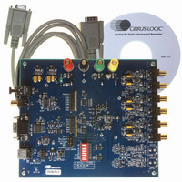
CDB4365
Description
EVALUATION BOARD FOR CS4365
Manufacturer
Cirrus Logic Inc
Specifications of CDB4365
Number Of Dac's
6
Number Of Bits
24
Outputs And Type
6, Differential
Sampling Rate (per Second)
192k
Data Interface
Serial
Dac Type
Voltage
Voltage Supply Source
Analog and Digital
Operating Temperature
-40°C ~ 85°C
Utilized Ic / Part
CS4365
Description/function
Audio D/A
Operating Supply Voltage
5 V
Product
Audio Modules
For Use With/related Products
CS4365
Lead Free Status / RoHS Status
Contains lead / RoHS non-compliant
Lead Free Status / RoHS Status
Lead free / RoHS Compliant, Contains lead / RoHS non-compliant
Other names
598-1779


DS670F2
6.8.5 DSD Auto-Mute (DAMUTE)
6.8.6 MUTE Polarity and DETECT (MUTEP1:0)
6.9
6.9.1 Mute (MUTE_xx)
Reserved
0
7
Mute Control (address 09h)
Function:
When set to 1 (default), the Digital-to-Analog converter output will mute following the reception of 256 re-
peated 8-bit DSD mute patterns (as defined in the SACD specification).
A single bit not fitting the repeated mute pattern (mentioned above) will release the mute. Detection and
muting is done independently for each channel. The quiescent voltage on the output will be retained, and
the Mute Control pin will go active during the mute period.
Default = 00
00 - Auto polarity detect, selected from MUTEC1 pin
01 - Reserved
10 - Active low mute polarity
11 - Active high mute polarity
Function:
Auto mute polarity detect (00)
See
Active low mute polarity (10)
When RST is low, the outputs are high impedance and will need to be biased active. Once reset has been
released and after this bit is set, the MUTEC output pins will be active low polarity.
Active high mute polarity (11)
At reset time, the outputs are high impedance and will need to be biased active. Once reset has been
released and after this bit is set, the MUTEC output pins will be active high polarity.
Default = 0
0 - Disabled
1 - Enabled
Function:
The Digital-to-Analog converter output will mute when enabled. The quiescent voltage on the output will
be retained. The muting function is affected, similarly to attenuation changes, by the Soft and Zero Cross
bits. The MUTE pins will go active during the mute period according to the MUTEC bits.
Section 4.11 “The MUTEC Outputs” on page 29
Reserved
6
0
MUTE_B3
5
0
MUTE_A3
0
4
MUTE_B2
for description.
3
0
MUTE_A2
2
0
MUTE_B1
0
1
MUTE_A1
CS4365
0
0
41
Related parts for CDB4365
Image
Part Number
Description
Manufacturer
Datasheet
Request
R

Part Number:
Description:
Development Kit
Manufacturer:
Cirrus Logic Inc
Datasheet:
Part Number:
Description:
Development Kit
Manufacturer:
Cirrus Logic Inc
Datasheet:


Part Number:
Description:
High-efficiency PFC + Fluorescent Lamp Driver Reference Design
Manufacturer:
Cirrus Logic Inc
Datasheet:
Part Number:
Description:
Development Kit
Manufacturer:
Cirrus Logic Inc
Datasheet:
Part Number:
Description:
Development Kit
Manufacturer:
Cirrus Logic Inc
Datasheet:

Part Number:
Description:
Development Kit
Manufacturer:
Cirrus Logic Inc
Datasheet:
Part Number:
Description:
Development Kit
Manufacturer:
Cirrus Logic Inc
Datasheet:
Part Number:
Description:
Development Kit
Manufacturer:
Cirrus Logic Inc
Datasheet:
Part Number:
Description:
Development Kit
Manufacturer:
Cirrus Logic Inc
Datasheet:

Part Number:
Description:
EVALUATION BOARD FOR CS8427
Manufacturer:
Cirrus Logic Inc
Datasheet:

Part Number:
Description:
BOARD EVAL FOR CS8416 RCVR
Manufacturer:
Cirrus Logic Inc
Datasheet:

Part Number:
Description:
EVALUATION BOARD FOR CS8420
Manufacturer:
Cirrus Logic Inc
Datasheet:

Part Number:
Description:
KIT DEVELOPMENT EP9315 ARM9
Manufacturer:
Cirrus Logic Inc
Datasheet:

Part Number:
Description:
KIT DEVELOPMENT EP9302 ARM9
Manufacturer:
Cirrus Logic Inc
Datasheet: