STEVAL-ILL027V1 STMicroelectronics, STEVAL-ILL027V1 Datasheet - Page 13
STEVAL-ILL027V1
Manufacturer Part Number
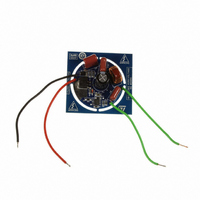
STEVAL-ILL027V1
Description
BOARD EVAL LED DRIVER FOR L6562A
Manufacturer
STMicroelectronics
Datasheets
1.L6562ADTR.pdf
(26 pages)
2.STEVAL-ILL027V1.pdf
(4 pages)
3.STEVAL-ILL027V1.pdf
(23 pages)
Specifications of STEVAL-ILL027V1
Design Resources
STEVAL-ILL027V1 Schematics STEVAL-ILL027V1 BOM STEVAL-ILL027V1 Gerber Files
Current - Output / Channel
260mA
Outputs And Type
1, Non-Isolated
Voltage - Output
70V
Features
Short-Circuit Protection
Voltage - Input
120VAC
Utilized Ic / Part
L6562A
Product
Display Modules
Lead Free Status / RoHS Status
Lead free by exemption / RoHS compliant by exemption
Other names
497-10170


L6562A
7
7.1
Application information
Overvoltage protection
Under steady-state conditions, the voltage control loop keeps the output voltage Vo of a
PFC pre-regulator close to its nominal value, set by the resistors R1 and R2 of the output
divider. Neglecting ripple components, the current through R1, I
I
2.5V, also the voltage at pin INV will be 2.5V, then:
Equation 1
If the output voltage experiences an abrupt change ∆Vo > 0 due to a load drop, the voltage
at pin INV will be kept at 2.5V by the local feedback of the error amplifier, a network
connected between pins INV and COMP that introduces a long time constant to achieve
high PF (this is why ∆Vo can be large). As a result, the current through R2 will remain equal
to 2.5/R2 but that through R1 will become:
Equation 2
The difference current ∆I
network and enter the error amplifier output (pin COMP). This current is monitored inside
the device and if it reaches about 24µA the output voltage of the multiplier is forced to
decrease, thus smoothly reducing the energy delivered to the output. As the current
exceeds 27µA, the OVP is triggered (Dynamic OVP): the gate-drive is forced low to switch
off the external power transistor and the IC put in an idle state. This condition is maintained
until the current falls below approximately 7µA, which re-enables the internal starter and
allows switching to restart. The output ∆Vo that is able to trigger the Dynamic OVP function
is then:
Equation 3
An important advantage of this technique is that the OV level can be set independently of
the regulated output voltage: the latter depends on the ratio of R1 to R2, the former on the
individual value of R1. Another advantage is the precision: the tolerance of the detection
current is 13%, i.e. 13% tolerance on ∆Vo. Since ∆Vo << Vo, the tolerance on the absolute
value will be proportionally reduced.
Example: Vo = 400V, ∆Vo = 40V. Then: R1 = 40V/27µA
R2 = 1.5 MΩ ·2.5/(400-2.5) = 9.43kΩ. The tolerance on the OVP level due to the L6562A will
be 40·0.13 = 5.3V, that is ± 1.2%.
R2
. Considering that the non-inverting input of the error amplifier is internally referenced at
R1
=I'
R1
-I
I
R2
R2
=I'
I'
=
R1
∆V
R1
I
O
R1
=
-I
= R1 · 20 · 10
R1
V
--------------------------------------- -
=
O
= ∆Vo/R1 will flow through the compensation
2.5
------- -
R2
–
2.5
R1
=
+
V
--------------------- -
∆
O
V
- 6
R1
–
O
≈
2.5
1.5MΩ ;
R1
, equals that through R2,
Application information
13/26
Related parts for STEVAL-ILL027V1
Image
Part Number
Description
Manufacturer
Datasheet
Request
R

Part Number:
Description:
BOARD EVAL FOR MEMS SENSORS
Manufacturer:
STMicroelectronics
Datasheet:

Part Number:
Description:
KIT DEV STARTER ST10F276Z5
Manufacturer:
STMicroelectronics
Datasheet:

Part Number:
Description:
BOARD EVAL HDMI $ VIDEO SWITCH
Manufacturer:
STMicroelectronics
Datasheet:

Part Number:
Description:
BOARD DEMO ACCELEROMETER DIL24
Manufacturer:
STMicroelectronics
Datasheet:

Part Number:
Description:
BOARD STLM75/STDS75/ST72F651
Manufacturer:
STMicroelectronics
Datasheet:

Part Number:
Description:
EVAL BOARD 3AXIS MEMS ACCELLRMTR
Manufacturer:
STMicroelectronics
Datasheet:

Part Number:
Description:
BOARD EVAL 8BIT MICRO + TDE1708
Manufacturer:
STMicroelectronics
Datasheet:

Part Number:
Description:
EVAL BOARD A/D TS4657
Manufacturer:
STMicroelectronics
Datasheet:

Part Number:
Description:
BOARD ADAPTER 20DIP LIS3LV02DL
Manufacturer:
STMicroelectronics
Datasheet:

Part Number:
Description:
BOARD DEMO STM8S207R6/LIS331DLH
Manufacturer:
STMicroelectronics
Datasheet:

Part Number:
Description:
STMicroelectronics [RIPPLE-CARRY BINARY COUNTER/DIVIDERS]
Manufacturer:
STMicroelectronics
Datasheet:
Part Number:
Description:
STMicroelectronics [LIQUID-CRYSTAL DISPLAY DRIVERS]
Manufacturer:
STMicroelectronics
Datasheet:
Part Number:
Description:
BOARD EVAL FOR MEMS SENSORS
Manufacturer:
STMicroelectronics
Datasheet: