IRPLLED1 International Rectifier, IRPLLED1 Datasheet - Page 11
IRPLLED1
Manufacturer Part Number
IRPLLED1
Description
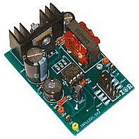
BOARD EVALUATION FOR IRS2540PBF
Manufacturer
International Rectifier
Specifications of IRPLLED1
Current - Output / Channel
1.5A
Outputs And Type
1, Non-Isolated
Voltage - Output
24V
Features
Dimmable
Voltage - Input
50 ~ 170V
Utilized Ic / Part
IRS2540PBF
Core Chip
IRS2540, IRS2541, IRS25401
Topology
Buck (Step Down)
No. Of Outputs
1
Output Current
1.5A
Output Voltage
500mV
Dimming Control Type
PWM
Development Tool Type
Hardware - Eval/Demo Board
Lead Free Status / RoHS Status
Contains lead / RoHS compliant by exemption


Fig. 15 Iout = 350mA, Vin = 100V, Vout = 16.85V, L = 470uH, COUT = 33uF
L1 and COUT need to be chosen so that enough energy is stored to supply the load during t_HO_on while
maintaining current control accuracy. A lower value of L1 requires a larger value of COUT.
Since this evaluation board is designed to handle a load current no higher then 1.5A, off the shelf inductors are
available. To minimize or eliminate any effects of eddy currents, a custom inductor for this application was
designed by VOGT. Values in the order of 1mH or more of inductor that can handle this amount of current are not
readily available and tend to be bulky and costly. With too small an inductor (of 100uH or less) the COUT
capacitor would need to be in the order of hundreds of micro Farads to maintain good current regulation.
Additionally with a smaller inductance, the ripple current seen by the capacitor would be quite large, which would
shorten the life of the capacitor if an electrolytic were used.
Because of these considerations an inductor of 470uH and an output capacitance of 33uF were chosen to
accommodate the 1.5A load current. The current ripple associated with 470uH is relatively small so the board can
be operated with or without output capacitance at the lower current ratings.
5. MOSFET vs Diode for the low side switch
The IRS2540/1 has been designed so that it can drive a low side MOSFET and a high side MOSFET. Alternatively
the low side FET can be replaced by a freewheeling diode as shown in Fig. 16. This may yield a lower cost system,
but there are some efficiency tradeoffs to be considered, particularly for higher load currents. The system efficiency
is directly influenced by several system parameters including operating frequency, load current, and input voltage.
In this evaluation board a fast recovery power diode is used for the lower switch.
A major parameter to consider is the reverse recovery time of the diode in comparison to the body diode of the FET
it replaces. The diode intrinsically has a much shorter reverse recovery time since the device is specifically designed
for this, where as the body diode is a parasitic element that originates from basic processing technology and
typically has inferior characteristics, in terms of forward drop, reverse recovery, and power handling capabilities.
RD-0608
11
www.irf.com
Related parts for IRPLLED1
Image
Part Number
Description
Manufacturer
Datasheet
Request
R

Part Number:
Description:
SCHOTTKY RECTIFIER
Manufacturer:
International Rectifier Corp.
Datasheet:
Part Number:
Description:
SCHOTTKY RECTIFIER
Manufacturer:
International Rectifier Corp.
Datasheet:
Part Number:
Description:
SCHOTTKY RECTIFIER
Manufacturer:
International Rectifier Corp.
Datasheet:
Part Number:
Description:
SCHOTTKY RECTIFIER
Manufacturer:
International Rectifier Corp.
Datasheet:
Part Number:
Description:
SCHOTTKY RECTIFIER
Manufacturer:
International Rectifier Corp.
Datasheet:
Part Number:
Description:
SCHOTTKY RECTIFIER
Manufacturer:
International Rectifier Corp.
Datasheet:
Part Number:
Description:
SCHOTTKY RECTIFIER
Manufacturer:
International Rectifier Corp.
Datasheet:
Part Number:
Description:
SCHOTTKY RECTIFIER
Manufacturer:
International Rectifier Corp.
Datasheet:
Part Number:
Description:
SCHOTTKY RECTIFIER
Manufacturer:
International Rectifier Corp.
Datasheet:
Part Number:
Description:
SCHOTTKY RECTIFIER
Manufacturer:
International Rectifier Corp.
Datasheet:
Part Number:
Description:
SCHOTTKY RECTIFIER
Manufacturer:
International Rectifier Corp.
Datasheet:
Part Number:
Description:
SCHOTTKY RECTIFIER
Manufacturer:
International Rectifier Corp.
Datasheet:
Part Number:
Description:
SCHOTTKY RECTIFIER
Manufacturer:
International Rectifier Corp.
Datasheet:
Part Number:
Description:
SCHOTTKY RECTIFIER
Manufacturer:
International Rectifier Corp.
Datasheet:
Part Number:
Description:
SCHOTTKY RECTIFIER
Manufacturer:
International Rectifier Corp.
Datasheet: