IRPLLED1 International Rectifier, IRPLLED1 Datasheet - Page 17
IRPLLED1
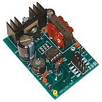
Manufacturer Part Number
IRPLLED1
Description
BOARD EVALUATION FOR IRS2540PBF
Manufacturer
International Rectifier
Specifications of IRPLLED1
Current - Output / Channel
1.5A
Outputs And Type
1, Non-Isolated
Voltage - Output
24V
Features
Dimmable
Voltage - Input
50 ~ 170V
Utilized Ic / Part
IRS2540PBF
Core Chip
IRS2540, IRS2541, IRS25401
Topology
Buck (Step Down)
No. Of Outputs
1
Output Current
1.5A
Output Voltage
500mV
Dimming Control Type
PWM
Development Tool Type
Hardware - Eval/Demo Board
Lead Free Status / RoHS Status
Contains lead / RoHS compliant by exemption


During an open circuit condition, without the watchdog timer, the HO output would remain high at all times and the
charge stored in the bootstrap capacitor (CBOOT) would slowly leak until reaching zero, thus eliminating the
floating power supply for the high side driver. To maintain sufficient charge on CBOOT, a watchdog timer has been
implemented. In the condition where VIFB remains below VIFBTH, the HO output will be forced low roughly after
20µs and the LO output forced high. This toggling of the outputs will last for 1µs to maintain and replenish
sufficient charge on CBOOT.
Fig. 21 Illustration of Watchdog Timer
The bootstrap capacitor value needs to be chosen so that it maintains sufficient charge for at least the 20µs interval
until the watchdog timer allows the capacitor to recharge. If the capacitor value is too small, the charge will fully
dissipate in less than 20µs. The bootstrap capacitor should be at least 100nF. A larger value within reason can be
used if preferred.
The bootstrap diode should be a fast recovery, if not an ultrafast recovery component to maintain good efficiency.
Since the cathode of the bootstrap diode will be switching between COM and VBUS + 14V, the reverse recovery
time of this diode is of critical importance. For additional information concerning the bootstrap components, refer to
the Design Tip (DT 98-2), “Bootstrap Component Selection For Control ICs” at
www.irf.com
under Design
Support.
8. Enable Pin
The enable pin can be used for dimming or open-circuit protection. When the ENN pin is held low the IRS2540
remains in a fully functional state with no alterations to the operating environment. To disable the control feedback
and regulation a voltage greater than VENTH (approximately 2.5V) needs to be applied to the ENN pin. With the
chip in a disabled state the HO output will remain low and the LO output will remain high to prevent VS from
floating, in addition to maintaining charge on the bootstrap capacitor if a MOSFET is used for the lower switch.
The threshold for disabling the IRS2540/1 has been set to 2.5V to enhance immunity to any externally generated
noise or application ground noise and also makes it possible receive a drive signal from a microcontroller.
Dimming Mode
To achieve dimming a signal with constant frequency and set duty cycle can be fed into the ENN pin. There is a
direct linear relationship between the average load current and duty cycle if no output capacitor is used in the circuit.
A large output capacitor tends to increase the minium dim level because some current continues to supply the LEDs
from this capacitor during the off phase of the PWM dimming. With no output capacitor, if the ratio is 50% then
50% of the maximum set light output will be emitted. Similarly if the ratio is 30% then 70% of the maximum set
light output will be realized. A sufficiently high frequency of the dimming signal must be chosen to avoid visible
RD-0608
17
www.irf.com
Related parts for IRPLLED1
Image
Part Number
Description
Manufacturer
Datasheet
Request
R

Part Number:
Description:
SCHOTTKY RECTIFIER
Manufacturer:
International Rectifier Corp.
Datasheet:
Part Number:
Description:
SCHOTTKY RECTIFIER
Manufacturer:
International Rectifier Corp.
Datasheet:
Part Number:
Description:
SCHOTTKY RECTIFIER
Manufacturer:
International Rectifier Corp.
Datasheet:
Part Number:
Description:
SCHOTTKY RECTIFIER
Manufacturer:
International Rectifier Corp.
Datasheet:
Part Number:
Description:
SCHOTTKY RECTIFIER
Manufacturer:
International Rectifier Corp.
Datasheet:
Part Number:
Description:
SCHOTTKY RECTIFIER
Manufacturer:
International Rectifier Corp.
Datasheet:
Part Number:
Description:
SCHOTTKY RECTIFIER
Manufacturer:
International Rectifier Corp.
Datasheet:
Part Number:
Description:
SCHOTTKY RECTIFIER
Manufacturer:
International Rectifier Corp.
Datasheet:
Part Number:
Description:
SCHOTTKY RECTIFIER
Manufacturer:
International Rectifier Corp.
Datasheet:
Part Number:
Description:
SCHOTTKY RECTIFIER
Manufacturer:
International Rectifier Corp.
Datasheet:
Part Number:
Description:
SCHOTTKY RECTIFIER
Manufacturer:
International Rectifier Corp.
Datasheet:
Part Number:
Description:
SCHOTTKY RECTIFIER
Manufacturer:
International Rectifier Corp.
Datasheet:
Part Number:
Description:
SCHOTTKY RECTIFIER
Manufacturer:
International Rectifier Corp.
Datasheet:
Part Number:
Description:
SCHOTTKY RECTIFIER
Manufacturer:
International Rectifier Corp.
Datasheet:
Part Number:
Description:
SCHOTTKY RECTIFIER
Manufacturer:
International Rectifier Corp.
Datasheet: