IRPLLED1 International Rectifier, IRPLLED1 Datasheet - Page 22
IRPLLED1
Manufacturer Part Number
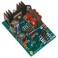
IRPLLED1
Description
BOARD EVALUATION FOR IRS2540PBF
Manufacturer
International Rectifier
Specifications of IRPLLED1
Current - Output / Channel
1.5A
Outputs And Type
1, Non-Isolated
Voltage - Output
24V
Features
Dimmable
Voltage - Input
50 ~ 170V
Utilized Ic / Part
IRS2540PBF
Core Chip
IRS2540, IRS2541, IRS25401
Topology
Buck (Step Down)
No. Of Outputs
1
Output Current
1.5A
Output Voltage
500mV
Dimming Control Type
PWM
Development Tool Type
Hardware - Eval/Demo Board
Lead Free Status / RoHS Status
Contains lead / RoHS compliant by exemption


until the end of the current HO cycle as shown in the waveform diagram below. The reason for this is to avoid the
possibility off ENN transitioning from low to high at the exact time that HO transitions from low to high, which may
trigger the HO output to latch up under a low VBS supply condition. This is caused by propagation delays that exist
inside the IC. RSYNC and DSYNC are not necessary in non-dimming applications. Synchronization as described will
not affect the operation or dimming functionality of the circuit. It will serve only to protect the circuit against a
possible fault condition, without any detrimental effect to operation.
Fig. 28a: Dimming Syncronization Waveforms.
9. Open circuit protection
Fig. 29 Open Circuit Protection Scheme
By using the suggested voltage divider, capacitor, and zener diode, the designer can virtually clamp the output
voltage at any desired value. If there is no load to clamp the output voltage, the positive output terminal will rise to
the input bus voltage.
The above circuit is able to limit the output voltage in this situation. However it should be noted reducing the output
voltage does not prevent the possibility of electric shock in non-isolated systems! Therefore an IRS2540 based
Buck LED driver running directly off line would still be an electric shock hazard and it would not be safe to
attempt to replace the LEDs if such a system were powered. In non-isolated systems, additional mechanical
protection is required to ensure that access to the LEDs is not possible or alternative a mechanical isolation system
could be used to disconnect the LEDs completely from the ballast for safe access. In an illuminated sign for
example, this would be a reasonable approach.
The open circuit protection system described in this section can only be an effective safety feature in a system where
the IRS2540 Buck stage is used as a back end stage supplied by an already isolated DC source. This scheme also
conflicts with the synchronization operation described in the previous section, therefore this over-voltage protection
scheme is less effective in dimming systems where the RSYNC and DSYNC modification has been added.
RD-0608
22
www.irf.com
Related parts for IRPLLED1
Image
Part Number
Description
Manufacturer
Datasheet
Request
R

Part Number:
Description:
SCHOTTKY RECTIFIER
Manufacturer:
International Rectifier Corp.
Datasheet:
Part Number:
Description:
SCHOTTKY RECTIFIER
Manufacturer:
International Rectifier Corp.
Datasheet:
Part Number:
Description:
SCHOTTKY RECTIFIER
Manufacturer:
International Rectifier Corp.
Datasheet:
Part Number:
Description:
SCHOTTKY RECTIFIER
Manufacturer:
International Rectifier Corp.
Datasheet:
Part Number:
Description:
SCHOTTKY RECTIFIER
Manufacturer:
International Rectifier Corp.
Datasheet:
Part Number:
Description:
SCHOTTKY RECTIFIER
Manufacturer:
International Rectifier Corp.
Datasheet:
Part Number:
Description:
SCHOTTKY RECTIFIER
Manufacturer:
International Rectifier Corp.
Datasheet:
Part Number:
Description:
SCHOTTKY RECTIFIER
Manufacturer:
International Rectifier Corp.
Datasheet:
Part Number:
Description:
SCHOTTKY RECTIFIER
Manufacturer:
International Rectifier Corp.
Datasheet:
Part Number:
Description:
SCHOTTKY RECTIFIER
Manufacturer:
International Rectifier Corp.
Datasheet:
Part Number:
Description:
SCHOTTKY RECTIFIER
Manufacturer:
International Rectifier Corp.
Datasheet:
Part Number:
Description:
SCHOTTKY RECTIFIER
Manufacturer:
International Rectifier Corp.
Datasheet:
Part Number:
Description:
SCHOTTKY RECTIFIER
Manufacturer:
International Rectifier Corp.
Datasheet:
Part Number:
Description:
SCHOTTKY RECTIFIER
Manufacturer:
International Rectifier Corp.
Datasheet:
Part Number:
Description:
SCHOTTKY RECTIFIER
Manufacturer:
International Rectifier Corp.
Datasheet: