IRPLLED1 International Rectifier, IRPLLED1 Datasheet - Page 18
IRPLLED1
Manufacturer Part Number
IRPLLED1
Description
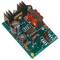
BOARD EVALUATION FOR IRS2540PBF
Manufacturer
International Rectifier
Specifications of IRPLLED1
Current - Output / Channel
1.5A
Outputs And Type
1, Non-Isolated
Voltage - Output
24V
Features
Dimmable
Voltage - Input
50 ~ 170V
Utilized Ic / Part
IRS2540PBF
Core Chip
IRS2540, IRS2541, IRS25401
Topology
Buck (Step Down)
No. Of Outputs
1
Output Current
1.5A
Output Voltage
500mV
Dimming Control Type
PWM
Development Tool Type
Hardware - Eval/Demo Board
Lead Free Status / RoHS Status
Contains lead / RoHS compliant by exemption


flashing or “strobe light” effect. A signal around 1kHz from zero to 5V is recommended. For this evaluation board, a
fully adjustable (0% to 100% duty cycle) PWM wave generator is suggested but this is not included as part of the
evaluation board. The following circuit is a simple enable pin dimming signal generator.
If an external supply for VCC is used, the minimum amount of dimming achievable (light output approaches 0%)
will be determined by the “on” time of the HO output, when in a fully functional regulating state. To maintain
reliable dimming, it is recommended to keep the “off” time of the enable signal at least 10 times that of the HO “on”
time. For example, if the application is running at 75kHz with an input voltage of 100V and an output voltage of
20V, the HO “on” time will be 2.7µs (one-fourth of the period – see calculations below) according to standard buck
topology theory. This will set the minimum “off” time of the enable signal to 27µs.
If the IRS2540 is supplied from the output, a large enough capacitor on VCC is required to maintain sufficient
current while in a disabled state. For this evaluation board where the IC supply comes from the output, a 10uF
capacitor is used to ensure continued operation while disabled. The output is capable of dropping to roughly 10V. A
“strobe light” effect in the LEDs may be observed if VCC drops too much or if the dimming frequency is too low.
www.irf.com
Fig. 22 Suggested PWM Driver (not included in IRPLLED1.5X2)
COM
VBUS
Duty
HO
on
C2
C1
Cycle
time
=
R1
R3
R7
20
=
RD-0608
%
V
V
out
in
R4
R2
*
1
∗
IN1(+)
GND
OUT1
IN1(-)
75
100
1
2
3
4
kHz
=
IC2
100
=
20
2
V
V
7 .
8
7
6
5
VCC
OUT2
IN2(-)
IN2(+)
µ
*
s
100
R6
=
CVCC4
R5
VR1
20
%
CVCC3
DEN2
RS
ENN pin
Out to
18
Related parts for IRPLLED1
Image
Part Number
Description
Manufacturer
Datasheet
Request
R

Part Number:
Description:
SCHOTTKY RECTIFIER
Manufacturer:
International Rectifier Corp.
Datasheet:
Part Number:
Description:
SCHOTTKY RECTIFIER
Manufacturer:
International Rectifier Corp.
Datasheet:
Part Number:
Description:
SCHOTTKY RECTIFIER
Manufacturer:
International Rectifier Corp.
Datasheet:
Part Number:
Description:
SCHOTTKY RECTIFIER
Manufacturer:
International Rectifier Corp.
Datasheet:
Part Number:
Description:
SCHOTTKY RECTIFIER
Manufacturer:
International Rectifier Corp.
Datasheet:
Part Number:
Description:
SCHOTTKY RECTIFIER
Manufacturer:
International Rectifier Corp.
Datasheet:
Part Number:
Description:
SCHOTTKY RECTIFIER
Manufacturer:
International Rectifier Corp.
Datasheet:
Part Number:
Description:
SCHOTTKY RECTIFIER
Manufacturer:
International Rectifier Corp.
Datasheet:
Part Number:
Description:
SCHOTTKY RECTIFIER
Manufacturer:
International Rectifier Corp.
Datasheet:
Part Number:
Description:
SCHOTTKY RECTIFIER
Manufacturer:
International Rectifier Corp.
Datasheet:
Part Number:
Description:
SCHOTTKY RECTIFIER
Manufacturer:
International Rectifier Corp.
Datasheet:
Part Number:
Description:
SCHOTTKY RECTIFIER
Manufacturer:
International Rectifier Corp.
Datasheet:
Part Number:
Description:
SCHOTTKY RECTIFIER
Manufacturer:
International Rectifier Corp.
Datasheet:
Part Number:
Description:
SCHOTTKY RECTIFIER
Manufacturer:
International Rectifier Corp.
Datasheet:
Part Number:
Description:
SCHOTTKY RECTIFIER
Manufacturer:
International Rectifier Corp.
Datasheet: