LM3552SDEV National Semiconductor, LM3552SDEV Datasheet - Page 9
LM3552SDEV
Manufacturer Part Number
LM3552SDEV
Description
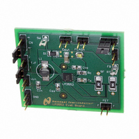
BOARD EVALUATION LM3552SD
Manufacturer
National Semiconductor
Series
PowerWise®r
Specifications of LM3552SDEV
Current - Output / Channel
700mA
Outputs And Type
1, Non-Isolated
Voltage - Output
4 V
Features
Flash Timeout Protection
Voltage - Input
2.7 ~ 5.5V
Utilized Ic / Part
LM3552
Core Chip
LM3552
Topology
Boost
No. Of Outputs
1
Output Current
1A
Input Voltage
2.7V To 5.5V
Development Tool Type
Hardware - Eval/Demo Board
Mcu Supported Families
LM3552
Lead Free Status / RoHS Status
Not applicable / Not applicable


the output will droop at a rate determined by the value of the
output capacitor and current leakage through the OVP pin and
any other leakage path. When the output voltage drops to
10.6V(typ), switching will resume. The LM3551 and LM3552
will go back into OVP if the failure is still present resulting in
a pulsed output condition.
Note: To disable OVP, ground to OVP pin. CAUTION: The LM3551 and
Under-Voltage Protection (UVP)
Both the LM3551 and LM3552 have under-voltage protection
circuitry (UVP). This protects the NMOS power device during
startup and shutdown by preventing operation at voltages
less than the minimum input voltage. The UVP protection is
enabled at 2.48V(typ.) and will not disable until the input volt-
age rises above 2.58V(typ.) .
Torch/Flash Pin (T/F)
The TORCH/FLASH pin (T/F) controls whether the LM3551/2
is in continuous torch mode, or in flash mode. A logic '0' places
the part into torch mode and a logic '1' places the part into
flash mode. There are no pull-ups or pull-downs internally
connected to T/F. When placed into torch mode, FET-T is
enabled allowing the current set by R
FET-F is not enabled. Flash mode enables both FET-T and
FET-F allowing the sum total of the current set by the two
external resistors, R
LM3552 may be damaged if an OVP condition occurs and OVP
is disabled.
T
and R
F
, to flow.
T
to flow. In torch mode,
Flash Timeout Protection Diagram
9
Flash Timeout Protection (FTP)
When SD is low(LM3551) or EN is high(LM3552), and T/F is
high, a current is output to an external capacitor, C
causes the voltage on the capacitor to rise. If the voltage
reaches Vtrip (1.16V(typ)), the timeout circuit forces the
INTERNAL_EN signal to go low, which in turn shuts-off the
low-side torch and flash FETs in addition to disabling the main
power SW FET. At such time, the LED will be turned off. The
part will remain disabled until SD is pulled high (LM3551) or
EN is pulled low (LM3552) and/or T/F is pulled low. At that
point, the part will return to normal operating mode. The dia-
gram below shows a first pulse which exceeds the timeout
period and internal_EN being driven low. The second FLASH
pulse is shorter than the timeout period and therefore the
voltage on C
ponent selection, please see the FLASH TIMEOUT EQUA-
TIONS below.
To disable the timeout function, ground the FTO pin.
FTO
C
T
FTO
ΔV
FTO
T
never reaches Vtrip. For information on com-
FTO
FTO
(µF) = T
= Desired Timeout Duration
= C
= 1.16V and I
FTO
FTO
× (ΔV
(sec.) × 1.21(µA/V)
FTO
FTO
÷ I
= 1.4µA
FTO
20151204
)
www.national.com
FTO
. This
Related parts for LM3552SDEV
Image
Part Number
Description
Manufacturer
Datasheet
Request
R


Part Number:
Description:
Precision Centigrade Temperature Sensors
Manufacturer:
National Semiconductor

Part Number:
Description:
Precision Centigrade Temperature Sensors
Manufacturer:
National Semiconductor Corporation
Datasheet:
Part Number:
Description:
National Semiconductor [8-Bit D/A Converter]
Manufacturer:
National Semiconductor
Datasheet:
Part Number:
Description:
National Semiconductor [Media Coprocessor]
Manufacturer:
National Semiconductor
Datasheet:
Part Number:
Description:
Digitally Controlled Tone and Volume Circuit with Stereo Audio Power Amplifier, Microphone Preamp Stage and National 3D Sound
Manufacturer:
National Semiconductor
Datasheet:
Part Number:
Description:
Digitally Controlled Tone and Volume Circuit with Stereo Audio Power Amplifier, Microphone Preamp Stage and National 3D Sound
Manufacturer:
National Semiconductor
Datasheet:
Part Number:
Description:
AC97 Rev 2 Codec with Sample Rate Conversion and National 3D Sound
Manufacturer:
National Semiconductor
Part Number:
Description:
Manufacturer:
National Semiconductor
Datasheet:
Part Number:
Description:
Manufacturer:
National Semiconductor
Datasheet:
Part Number:
Description:
General Purpose, Low Voltage, Low Power, Rail-to-Rail Output Operational Amplifiers
Manufacturer:
National Semiconductor
Datasheet:
Part Number:
Description:
8-bit 20 MSPS flash A/D converter.
Manufacturer:
National Semiconductor
Datasheet:
Part Number:
Description:
Low Noise Quad Operational Amplifier
Manufacturer:
National Semiconductor
Datasheet:
Part Number:
Description:
Quad Differential Line Receivers
Manufacturer:
National Semiconductor
Datasheet: