ATAVRQTOUCHX Atmel, ATAVRQTOUCHX Datasheet - Page 18
ATAVRQTOUCHX
Manufacturer Part Number
ATAVRQTOUCHX
Description
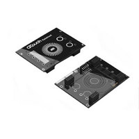
BOARD EVAL CAPACITIVE TOUCH
Manufacturer
Atmel
Series
QTouch™r
Specifications of ATAVRQTOUCHX
Sensor Type
Touch, Capacitive
Sensing Range
1 Slider, 1 Wheel, 2 Buttons
Interface
USB
Voltage - Supply
5V, USB
Embedded
Yes, MCU, 8-Bit
Utilized Ic / Part
AT90USB1287, ATxmega128A1
Silicon Manufacturer
Atmel
Silicon Family Name
ATxmega
Kit Contents
Board
Svhc
No SVHC (15-Dec-2010)
Core Architecture
AVR
Core Sub-architecture
AVR19
Kit Features
One Slider, One Wheel And 2
Rohs Compliant
Yes
Lead Free Status / RoHS Status
Lead free / RoHS Compliant
Sensitivity
-
Lead Free Status / Rohs Status
Lead free / RoHS Compliant
Available stocks
Company
Part Number
Manufacturer
Quantity
Price
Company:

Part Number:
ATAVRQTOUCHX
Manufacturer:
Atmel
Quantity:
135


Setting
Negative Drift
Positive Drift
5.3.6
If any key is found to have a significant drop in signal delta, (on the negative side), it is deemed to
be an error condition. If this condition persists for more than the positive recalibration delay, i.e.,
qt_pos_recal_delay period, then an automatic recalibration is carried out.
A counter is incremented each time the sensor delta is equal to the positive recalibration
threshold and stayed there for a specific number of acquisitions. When this counter reaches a
preset limit (the PRD value) the sensor is finally recalibrated. If on any acquisition the delta is
seen to be greater than the positive recalibration threshold level, the counter is cleared and the
positive drifting is performed.
For example, if the PRD value is 10, then the delta has to drop below the recalibration threshold
and stay there for 10 acquisitions in succession without going below the threshold level, before
the sensor is declared to be recalibrated.
Setting
Positive
Recalibration
Delay
5.4 Sensor specific settings
Apart from global settings as mentioned in the section above, touch sensing using QTouch library
could also be fine tuned by more number of configurable settings.
This section explains the settings that are specific to each sensor. For example, sensor 0 can
have a detect threshold (one of the sensor specific setting) that is different from sensor 1.
5.4.1
A sensor’s negative (detect) threshold defines how much its signal must drop below its reference
level to qualify as a potential touch detect. The final detection confirmation must however satisfy
the Detect Integrator (DI) limit. Larger threshold values desensitize sensors since the signal must
change more (i.e. requires larger touch) in order to exceed the threshold level. Conversely, lower
threshold levels make sensors more sensitive.
Threshold setting depends on the amount of signal swing that occurs when a sensor is touched.
Thicker front panels or smaller electrodes usually have smaller signal swing on touch, thus
require lower threshold levels.
Setting
Threshold
5.4.2
This setting is sensor detection hysteresis value. It is expressed as a percentage of the sensor
detection threshold setting. Once a sensor goes into detect its threshold level is reduced (by the
18
Positive Recalibration Delay
Detect threshold
Hysteresis
Variable name
threshold
Variable name
qt_neg_drift_rate
qt_pos_drift_rate
Variable name
qt_pos_recal_delay
Data Type
uint8_t
Data Type
uint8_t
uint8_t
Data Type
uint8_t
Unit
counts
Unit
Unit
200 ms
200 ms
cycles
Min
3
Min
1
1
Min
1
8207J-AT42-02/11
Max
255
Max
127
127
Max
255
Typical
10 – 20
Typical
20 (4s)
5 (1s)
Typical
3
Related parts for ATAVRQTOUCHX
Image
Part Number
Description
Manufacturer
Datasheet
Request
R


Part Number:
Description:
DEV KIT FOR AVR/AVR32
Manufacturer:
Atmel
Datasheet:

Part Number:
Description:
INTERVAL AND WIPE/WASH WIPER CONTROL IC WITH DELAY
Manufacturer:
ATMEL Corporation
Datasheet:
Part Number:
Description:
Low-Voltage Voice-Switched IC for Hands-Free Operation
Manufacturer:
ATMEL Corporation
Datasheet:
Part Number:
Description:
MONOLITHIC INTEGRATED FEATUREPHONE CIRCUIT
Manufacturer:
ATMEL Corporation
Datasheet:
Part Number:
Description:
AM-FM Receiver IC U4255BM-M
Manufacturer:
ATMEL Corporation
Datasheet:
Part Number:
Description:
Monolithic Integrated Feature Phone Circuit
Manufacturer:
ATMEL Corporation
Datasheet:
Part Number:
Description:
Multistandard Video-IF and Quasi Parallel Sound Processing
Manufacturer:
ATMEL Corporation
Datasheet:
Part Number:
Description:
High-performance EE PLD
Manufacturer:
ATMEL Corporation
Datasheet:
Part Number:
Description:
8-bit Flash Microcontroller
Manufacturer:
ATMEL Corporation
Datasheet:
Part Number:
Description:
2-Wire Serial EEPROM
Manufacturer:
ATMEL Corporation
Datasheet: