ATAVRQTOUCHX Atmel, ATAVRQTOUCHX Datasheet - Page 58
ATAVRQTOUCHX
Manufacturer Part Number
ATAVRQTOUCHX
Description
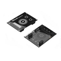
BOARD EVAL CAPACITIVE TOUCH
Manufacturer
Atmel
Series
QTouch™r
Specifications of ATAVRQTOUCHX
Sensor Type
Touch, Capacitive
Sensing Range
1 Slider, 1 Wheel, 2 Buttons
Interface
USB
Voltage - Supply
5V, USB
Embedded
Yes, MCU, 8-Bit
Utilized Ic / Part
AT90USB1287, ATxmega128A1
Silicon Manufacturer
Atmel
Silicon Family Name
ATxmega
Kit Contents
Board
Svhc
No SVHC (15-Dec-2010)
Core Architecture
AVR
Core Sub-architecture
AVR19
Kit Features
One Slider, One Wheel And 2
Rohs Compliant
Yes
Lead Free Status / RoHS Status
Lead free / RoHS Compliant
Sensitivity
-
Lead Free Status / Rohs Status
Lead free / RoHS Compliant
Available stocks
Company
Part Number
Manufacturer
Quantity
Price
Company:

Part Number:
ATAVRQTOUCHX
Manufacturer:
Atmel
Quantity:
135


Note:
Choice
available
design
Given the above requirements for the applications, the first step is to select the right library
variant required.
Step 1:
Select the Device that suits the requirements based on the touch sensing channels needed from
the library selection guide available at C:\ Program Files\Atmel\ Atmel_QTouch_Libaries_4.x\
Library_Selection_Guide.xls
Step 2:
From the Library_selection_Guide.xls list,, we see that there are a few variants of libraries
supported for AT Tiny device. Since the application requires 6 channels and rotor slider support,
one has to select a library variant which supports at least 6 channels or more. Hence we select
the 8 channel library which supports the required Port combination and the delay cycle preferred
which works out to be the variant
Step 3:
Defining the constants / symbols in the project space or modifying in touch_qm_config.h
In the host application file (say main.c), define the following constants and symbols
58
•
1. Some of these macro’s can be taken from the output of the Pin configurator tool from
libv1g1s1_8qm_4x_2y_krs_2rs.r90
#define _QMATRIX_
#define QT_NUM_CHANNELS
#define NUM_X_LINES
#define NUM_Y_LINES
#define NUM_X_PORTS
#define PORT_X_1
#define PORT_NUM_1
#define PORT_X_2
#define PORT_NUM_2
#define PORT_YA
#define PORT_YB
#define PORT_SMP
#define SMP_PIN
#define QT_DELAY_CYCLES
#define ROTOR_SLIDER_
#define QT_MAX_NUM_ROTORS_SLIDERS
QTouch Studio. Refer to section 5.8.2
of
for
ports
the
PORT_X_1 = B
PORT_X_2 = D
YA Line on PORTD
YB Line on PORTC
SMP Pin on PORTD pin 7
QT_DELAY_CYCLES of 4
8
4
2
2
B
1
D
2
D
C
D
7
4
2
Any pins that are not conflicting
with the host application and
follow the configuration supported
by library can be used.
This can be filled from the output
of the pin configurator tool in
QTouch Studio. Please refer to
section 5.8.2
8207J-AT42-02/11
Or
Related parts for ATAVRQTOUCHX
Image
Part Number
Description
Manufacturer
Datasheet
Request
R


Part Number:
Description:
DEV KIT FOR AVR/AVR32
Manufacturer:
Atmel
Datasheet:

Part Number:
Description:
INTERVAL AND WIPE/WASH WIPER CONTROL IC WITH DELAY
Manufacturer:
ATMEL Corporation
Datasheet:
Part Number:
Description:
Low-Voltage Voice-Switched IC for Hands-Free Operation
Manufacturer:
ATMEL Corporation
Datasheet:
Part Number:
Description:
MONOLITHIC INTEGRATED FEATUREPHONE CIRCUIT
Manufacturer:
ATMEL Corporation
Datasheet:
Part Number:
Description:
AM-FM Receiver IC U4255BM-M
Manufacturer:
ATMEL Corporation
Datasheet:
Part Number:
Description:
Monolithic Integrated Feature Phone Circuit
Manufacturer:
ATMEL Corporation
Datasheet:
Part Number:
Description:
Multistandard Video-IF and Quasi Parallel Sound Processing
Manufacturer:
ATMEL Corporation
Datasheet:
Part Number:
Description:
High-performance EE PLD
Manufacturer:
ATMEL Corporation
Datasheet:
Part Number:
Description:
8-bit Flash Microcontroller
Manufacturer:
ATMEL Corporation
Datasheet:
Part Number:
Description:
2-Wire Serial EEPROM
Manufacturer:
ATMEL Corporation
Datasheet: