ATAVRQTOUCHX Atmel, ATAVRQTOUCHX Datasheet - Page 43
ATAVRQTOUCHX
Manufacturer Part Number
ATAVRQTOUCHX
Description
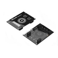
BOARD EVAL CAPACITIVE TOUCH
Manufacturer
Atmel
Series
QTouch™r
Specifications of ATAVRQTOUCHX
Sensor Type
Touch, Capacitive
Sensing Range
1 Slider, 1 Wheel, 2 Buttons
Interface
USB
Voltage - Supply
5V, USB
Embedded
Yes, MCU, 8-Bit
Utilized Ic / Part
AT90USB1287, ATxmega128A1
Silicon Manufacturer
Atmel
Silicon Family Name
ATxmega
Kit Contents
Board
Svhc
No SVHC (15-Dec-2010)
Core Architecture
AVR
Core Sub-architecture
AVR19
Kit Features
One Slider, One Wheel And 2
Rohs Compliant
Yes
Lead Free Status / RoHS Status
Lead free / RoHS Compliant
Sensitivity
-
Lead Free Status / Rohs Status
Lead free / RoHS Compliant
Available stocks
Company
Part Number
Manufacturer
Quantity
Price
Company:

Part Number:
ATAVRQTOUCHX
Manufacturer:
Atmel
Quantity:
135


RES_8_BIT, 0u
HYST_6_25, RES_8_BIT, 0u );
The channel numbers 0,2,3,4,6,7 are allocated to pins 0,2,3,4,6,7 of (D,C) port pair respectively.
Pins 1 and 5 of ports C and D can be used for user application. Similarly the channel numbers
12,13,14,15 are allocated to pins 4,5,6,7 of (B,A) port pair respectively. Pins 1, 2, 3 and 4 of ports
B and A are again unused by the QTouch library and can be used for user application.
5.6.6.5
The Pull-up circuit available (in AVR devices) for each GPIO pin has to be disabled before
QTouch acquisition is performed. For tinyAVR and megaAVR devices the Pull-up circuit for all
GPIO port pins are enabled and disabled together. When user needs to configure the pins that
are not used by QTouch library for his application, he may enable the Pull-up circuit after QTouch
measurements are performed and disable them before the touch acquisition starts once again (as
shown in the code snippet below).
For XMEGA devices the Pull-up circuit for each individual GPIO port pins can be configured
individually, by writing to the PINnCTRL register of the ports being used.
5.6.7
5.6.7.1
QTouch acquisition method libraries are available for different port combinations.
Some of the key constraints while configuring the sensors are
/* Disable pull-ups for all pins */
MCUCR
/* perform QTouch measurements */
qt_measure_sensors ( current_time_ms_touch );
/* Enable pull-ups for all pins */
•
/* enable a slider on channels 2 to 4
qt_enable_slider( CHANNEL_2, CHANNEL_4, AKS_GROUP_1, 16u, HYST_6_25,
/* enable a key on channel 6 */
qt_enable_key( CHANNEL_6, AKS_GROUP_2, 10u, HYST_6_25 );
/* enable a key on channel 7 */
qt_enable_key( CHANNEL_7, AKS_GROUP_2, 10u, HYST_6_25 );
/* enable a rotor on channels 12 to14
qt_enable_rotor(
/* enable a key on channel 15 */
qt_enable_key( CHANNEL_15, AKS_GROUP_2, 10u, HYST_6_25 );
MCUCR
Constraints
Rotors/sliders have to be connected on three adjacent channels. (e.g. (1,2,3) or (3,4,5)
…) within the same port. Possible combinations are (0,1,2), (1,2,3) for a configuration
which supports 4 channels. Possible combinations (0,1,2), (1,2,3), (2,3,4), (3,4,5), (4,5,6),
(5,6,7) for a configuration which supports 8 channels.
Disabling and Enabling of Pull-up for AVR devices
QTouch acquisition method constraints
|=
&=
);
(1u << PUD);
~ (1u << PUD);
CHANNEL_12,
//MCUCR_PUD = 1u;
CHANNEL_14,
//MCUCR_PUD = 0u;
*/
*/
AKS_GROUP_1,
16u,
43
Related parts for ATAVRQTOUCHX
Image
Part Number
Description
Manufacturer
Datasheet
Request
R


Part Number:
Description:
DEV KIT FOR AVR/AVR32
Manufacturer:
Atmel
Datasheet:

Part Number:
Description:
INTERVAL AND WIPE/WASH WIPER CONTROL IC WITH DELAY
Manufacturer:
ATMEL Corporation
Datasheet:
Part Number:
Description:
Low-Voltage Voice-Switched IC for Hands-Free Operation
Manufacturer:
ATMEL Corporation
Datasheet:
Part Number:
Description:
MONOLITHIC INTEGRATED FEATUREPHONE CIRCUIT
Manufacturer:
ATMEL Corporation
Datasheet:
Part Number:
Description:
AM-FM Receiver IC U4255BM-M
Manufacturer:
ATMEL Corporation
Datasheet:
Part Number:
Description:
Monolithic Integrated Feature Phone Circuit
Manufacturer:
ATMEL Corporation
Datasheet:
Part Number:
Description:
Multistandard Video-IF and Quasi Parallel Sound Processing
Manufacturer:
ATMEL Corporation
Datasheet:
Part Number:
Description:
High-performance EE PLD
Manufacturer:
ATMEL Corporation
Datasheet:
Part Number:
Description:
8-bit Flash Microcontroller
Manufacturer:
ATMEL Corporation
Datasheet:
Part Number:
Description:
2-Wire Serial EEPROM
Manufacturer:
ATMEL Corporation
Datasheet: