ATQT600 Atmel, ATQT600 Datasheet - Page 12
ATQT600
Manufacturer Part Number
ATQT600
Description
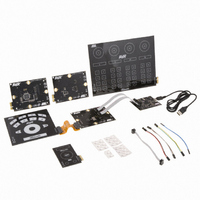
KIT EVAL TOUCH FOR QT600
Manufacturer
Atmel
Series
QTouch™r
Specifications of ATQT600
Sensor Type
Touch Screen
Interface
USB
Embedded
Yes, Other
Utilized Ic / Part
ATtiny88, ATmega324PA, ATxmega128A1
Processor To Be Evaluated
ATtiny88, ATmega324, ATxmega128
Data Bus Width
8 bit, 16 bit
Interface Type
USB
Maximum Operating Temperature
+ 85 C
Minimum Operating Temperature
- 40 C
Operating Supply Voltage
1.6 V to 3.6 V
Silicon Manufacturer
Atmel
Kit Application Type
Sensor
Application Sub Type
Touch Sensor
Kit Contents
USB Bridge, MCU Cards, Touchpad Cards
Svhc
No SVHC (15-Dec-2010)
Mcu Supported Families
ATtiny88,
Rohs Compliant
Yes
Lead Free Status / RoHS Status
Lead free / RoHS Compliant
Voltage - Supply
-
Sensitivity
-
Sensing Range
-
Lead Free Status / Rohs Status
Lead free / RoHS Compliant
Available stocks
Company
Part Number
Manufacturer
Quantity
Price
Company:

Part Number:
ATQT600
Manufacturer:
Atmel
Quantity:
135


10620D–AT42–04/09
General Advice
2-2
Figure 2-1.
Figure 2-2.
As a rule, the overall RC time constant of each sensor should be reduced as far as possible, while trying
to preserve at least a 1 k series resistor close to the sensor chip. A good rule-of-thumb is given in
Equation
Equation 2-3. Rule Of Thumb for RC Time Constant
The “Marginal” example in
about 5 time constants.
1. The factor of 5 ensures that each charge-transfer pulse settles to better than 99 percent, leaving just 1 percent of
charge subject to second order effects, such as the Rseries value, chip output drive strength, and so on..
2-3.
Measuring the Charge-transfer Pulses
Good and Bad Charge Pulses
Rseries_total * (Cx + Cp) <= 5 x Tcharge
Where:
Bad
Rseries_total is the total series connection from the sensor chip’s pin to the farthest
point on the sensor.
Cx + Cp represents the total capacitance that the sensor chip detects for the sensor
(that is, the sensor itself plus any parasitic capacitance). Measuring this can be done
for a first order approximation using a commercial capacitance bridge. A more
practical approach is to measure the pulse shapes as described above.
Tcharge varies somewhat from sensor chip to sensor chip, but a good estimate is
1 µs for zero- and one-dimensional sensors, and 2 µs for two-dimensional sensors.
Figure 2-2
represents about 3 time constants; the “Good” example represents
Marginal
(1)
Good
Touch Sensors Design Guide
Excellent
Related parts for ATQT600
Image
Part Number
Description
Manufacturer
Datasheet
Request
R

Part Number:
Description:
DEV KIT FOR AVR/AVR32
Manufacturer:
Atmel
Datasheet:

Part Number:
Description:
INTERVAL AND WIPE/WASH WIPER CONTROL IC WITH DELAY
Manufacturer:
ATMEL Corporation
Datasheet:
Part Number:
Description:
Low-Voltage Voice-Switched IC for Hands-Free Operation
Manufacturer:
ATMEL Corporation
Datasheet:
Part Number:
Description:
MONOLITHIC INTEGRATED FEATUREPHONE CIRCUIT
Manufacturer:
ATMEL Corporation
Datasheet:
Part Number:
Description:
AM-FM Receiver IC U4255BM-M
Manufacturer:
ATMEL Corporation
Datasheet:
Part Number:
Description:
Monolithic Integrated Feature Phone Circuit
Manufacturer:
ATMEL Corporation
Datasheet:
Part Number:
Description:
Multistandard Video-IF and Quasi Parallel Sound Processing
Manufacturer:
ATMEL Corporation
Datasheet:
Part Number:
Description:
High-performance EE PLD
Manufacturer:
ATMEL Corporation
Datasheet:
Part Number:
Description:
8-bit Flash Microcontroller
Manufacturer:
ATMEL Corporation
Datasheet:
Part Number:
Description:
2-Wire Serial EEPROM
Manufacturer:
ATMEL Corporation
Datasheet: