ATQT600 Atmel, ATQT600 Datasheet - Page 41
ATQT600
Manufacturer Part Number
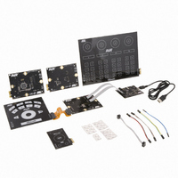
ATQT600
Description
KIT EVAL TOUCH FOR QT600
Manufacturer
Atmel
Series
QTouch™r
Specifications of ATQT600
Sensor Type
Touch Screen
Interface
USB
Embedded
Yes, Other
Utilized Ic / Part
ATtiny88, ATmega324PA, ATxmega128A1
Processor To Be Evaluated
ATtiny88, ATmega324, ATxmega128
Data Bus Width
8 bit, 16 bit
Interface Type
USB
Maximum Operating Temperature
+ 85 C
Minimum Operating Temperature
- 40 C
Operating Supply Voltage
1.6 V to 3.6 V
Silicon Manufacturer
Atmel
Kit Application Type
Sensor
Application Sub Type
Touch Sensor
Kit Contents
USB Bridge, MCU Cards, Touchpad Cards
Svhc
No SVHC (15-Dec-2010)
Mcu Supported Families
ATtiny88,
Rohs Compliant
Yes
Lead Free Status / RoHS Status
Lead free / RoHS Compliant
Voltage - Supply
-
Sensitivity
-
Sensing Range
-
Lead Free Status / Rohs Status
Lead free / RoHS Compliant
Available stocks
Company
Part Number
Manufacturer
Quantity
Price
Company:

Part Number:
ATQT600
Manufacturer:
Atmel
Quantity:
135


4.2.5
4.2.6
4.2.7
4.2.8
Touch Sensors Design Guide
Illumination Effects
Floating Conductive Items
Conductive Paints
Transparent Y Electrodes
With the planar construction of mutual-capacitance type electrodes it is fine to make holes in the X
portion of the electrode to allow light to shine though, much as described in
Effects” on page
Try not to remove too much of the X area or you risk making a dead spot in the key.
Transparent electrode materials also work well with this type of sensor if you take care to meet RC time
constant constraints (see
Mutual-capacitance type sensors are much less sensitive to floating metal as self-capacitance types.
The reason for this is that the measured field is localized between X and Y. However, it is still good
practice to avoid such risks, as described in
The considerations for the use of conductive paints described in
page 3-7
Transparent Y electrodes can end up with significant series resistance if made from materials like ITO or
Orgacon. This can be a problem due to excessive RC delay. Consider using printed silver or carbon
tracks or copper traces to add more than one connection point, if possible, to lower the resistance (see
Figure 4-9 on page
required transparent area, of course) is possible.
Figure 4-9.
apply.
Lowering Resistance with Extra Silver, Carbon or Copper Traces
3-5. The rules for LEDs are described in
4-9). Selective use of silver or copper over the top of the electrode (outside the
Section 2.1 “Charge Transfer” on page
R
total
= 5 x
s W
R
Digital Multimeter
Digital Multimeter
/sq
total
= 20 x
Section 3.2.6 “Floating Conductive Items” on page
s W
/sq
Mutual-capacitance Zero-dimensional Sensors
Section 2.4 “Nearby LEDs” on page
2-1).
Section 3.2.7 “Conductive Paints” on
Extra connection
reduces worst
resistance by 4 times
Section 3.2.5 “Illumination
Silver,
Carbon
or Copper
10620D–AT42–04/09
2-7.
3-6.
4-9
Related parts for ATQT600
Image
Part Number
Description
Manufacturer
Datasheet
Request
R

Part Number:
Description:
DEV KIT FOR AVR/AVR32
Manufacturer:
Atmel
Datasheet:

Part Number:
Description:
INTERVAL AND WIPE/WASH WIPER CONTROL IC WITH DELAY
Manufacturer:
ATMEL Corporation
Datasheet:
Part Number:
Description:
Low-Voltage Voice-Switched IC for Hands-Free Operation
Manufacturer:
ATMEL Corporation
Datasheet:
Part Number:
Description:
MONOLITHIC INTEGRATED FEATUREPHONE CIRCUIT
Manufacturer:
ATMEL Corporation
Datasheet:
Part Number:
Description:
AM-FM Receiver IC U4255BM-M
Manufacturer:
ATMEL Corporation
Datasheet:
Part Number:
Description:
Monolithic Integrated Feature Phone Circuit
Manufacturer:
ATMEL Corporation
Datasheet:
Part Number:
Description:
Multistandard Video-IF and Quasi Parallel Sound Processing
Manufacturer:
ATMEL Corporation
Datasheet:
Part Number:
Description:
High-performance EE PLD
Manufacturer:
ATMEL Corporation
Datasheet:
Part Number:
Description:
8-bit Flash Microcontroller
Manufacturer:
ATMEL Corporation
Datasheet:
Part Number:
Description:
2-Wire Serial EEPROM
Manufacturer:
ATMEL Corporation
Datasheet: