ATQT600 Atmel, ATQT600 Datasheet - Page 44
ATQT600
Manufacturer Part Number
ATQT600
Description
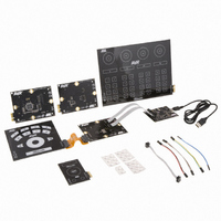
KIT EVAL TOUCH FOR QT600
Manufacturer
Atmel
Series
QTouch™r
Specifications of ATQT600
Sensor Type
Touch Screen
Interface
USB
Embedded
Yes, Other
Utilized Ic / Part
ATtiny88, ATmega324PA, ATxmega128A1
Processor To Be Evaluated
ATtiny88, ATmega324, ATxmega128
Data Bus Width
8 bit, 16 bit
Interface Type
USB
Maximum Operating Temperature
+ 85 C
Minimum Operating Temperature
- 40 C
Operating Supply Voltage
1.6 V to 3.6 V
Silicon Manufacturer
Atmel
Kit Application Type
Sensor
Application Sub Type
Touch Sensor
Kit Contents
USB Bridge, MCU Cards, Touchpad Cards
Svhc
No SVHC (15-Dec-2010)
Mcu Supported Families
ATtiny88,
Rohs Compliant
Yes
Lead Free Status / RoHS Status
Lead free / RoHS Compliant
Voltage - Supply
-
Sensitivity
-
Sensing Range
-
Lead Free Status / Rohs Status
Lead free / RoHS Compliant
Available stocks
Company
Part Number
Manufacturer
Quantity
Price
Company:

Part Number:
ATQT600
Manufacturer:
Atmel
Quantity:
135


10620D–AT42–04/09
Mutual-capacitance Zero-dimensional Sensors
4.3.3
4-12
Spring Method
A useful method for transferring the touch-sensitive region of a mutual-capacitance sensor, is to use a
conductive spring or hollow conductive tube to act as an X emitter, with the Y electrode placed centrally
on the substrate below the panel inside the X electrode (see
The spring should have an inner diameter of 8 to 10 mm. The Y electrode should be a circular pad with a
diameter of half the spring’s inner diameter.
The compressed length of the spring, and hence the distance from the inside of the panel to the front of
the PCB, should be less than 1 spring inner diameter. The pitch of the coils of the spring is not vitally
important, but generally try to have the gaps approximately the same size as the diameter of the spring
wire when the spring is compressed to its final position.
Figure 4-11. Using a Spring In a Mutual-capacitance Type Sensor
Neighboring coils can be arranged next to each other, ideally with a minimum center-to-center distance
of 1.5 x spring outer diameter
Note that the spring is not intended to compress when touched; it is always maintained in a compressed
state. The spring forms a static electrode that bridges the gap between the touch panel and the
component PCB. The change happens because the field inside the spring is redistributed during a touch
(see Figure 4-12).
Figure 4-12. Effect of a Touch With a Spring
1. This helps to keep cross-coupling between keys to a manageable level. Using continuous tube type X electrodes
will relax this requirement.
Y (Centre Pad
Half Diameter
Of Spring)
Control PCB
Panel
(1)
Field distributed
inside spring
.
No Touch
Field
Some of field diverted
Touch (Cx Reduced)
towards finger
Figure
4-11).
Touch Sensors Design Guide
X Emitter
(Conductive Spring,
Rubber, Foam or
Plastic Tube)
Control PCB
Front Panel
Related parts for ATQT600
Image
Part Number
Description
Manufacturer
Datasheet
Request
R

Part Number:
Description:
DEV KIT FOR AVR/AVR32
Manufacturer:
Atmel
Datasheet:

Part Number:
Description:
INTERVAL AND WIPE/WASH WIPER CONTROL IC WITH DELAY
Manufacturer:
ATMEL Corporation
Datasheet:
Part Number:
Description:
Low-Voltage Voice-Switched IC for Hands-Free Operation
Manufacturer:
ATMEL Corporation
Datasheet:
Part Number:
Description:
MONOLITHIC INTEGRATED FEATUREPHONE CIRCUIT
Manufacturer:
ATMEL Corporation
Datasheet:
Part Number:
Description:
AM-FM Receiver IC U4255BM-M
Manufacturer:
ATMEL Corporation
Datasheet:
Part Number:
Description:
Monolithic Integrated Feature Phone Circuit
Manufacturer:
ATMEL Corporation
Datasheet:
Part Number:
Description:
Multistandard Video-IF and Quasi Parallel Sound Processing
Manufacturer:
ATMEL Corporation
Datasheet:
Part Number:
Description:
High-performance EE PLD
Manufacturer:
ATMEL Corporation
Datasheet:
Part Number:
Description:
8-bit Flash Microcontroller
Manufacturer:
ATMEL Corporation
Datasheet:
Part Number:
Description:
2-Wire Serial EEPROM
Manufacturer:
ATMEL Corporation
Datasheet: