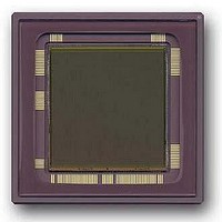
CYIL1SM4000-EVAL Cypress Semiconductor Corp, CYIL1SM4000-EVAL Datasheet - Page 15

CYIL1SM4000-EVAL
Manufacturer Part Number
CYIL1SM4000-EVAL
Description
BOARD EVAL IMAGE SENS LUPA-4000
Manufacturer
Cypress Semiconductor Corp
Specifications of CYIL1SM4000-EVAL
Sensor Type
CMOS Imaging, Monochrome
Sensing Range
4 Megapixel
Interface
SPI
Sensitivity
15 fps
Voltage - Supply
2.5 V ~ 3.3 V
Embedded
No
Utilized Ic / Part
LUPA-4000
Lead Free Status / RoHS Status
Contains lead / RoHS non-compliant
Lead Free Status / RoHS Status
Lead free / RoHS Compliant, Contains lead / RoHS non-compliant
3.5 Column amplifiers
The column amplifiers are designed for minimum power dissipation and minimum
loss of signal for this reason multiple biasing signals are needed.
The column amplifiers also have the “voltage-averaging” feature integrated. In case
of voltage averaging mode, the voltage average between 2 columns is taken and read
out. In this mode only 2:1 pixels have to be read out.
To achieve the voltage-averaging mode, an additional external digital signal called
“voltage-averaging” is required in combination with a bit from the SPI.
3.6 Analog to Digital Converter
The LUPA4000 has a two 10 bit flash analog digital converters running nominally at
33 Msamples/s. The ADC’s are electrically separated from the image sensor. The
inputs of the ADC should be tied externally to the outputs of the output amplifiers.
One ADC will sample the even columns and the other one will sample the odd
columns. Although the input range of the ADC is between 1V and 2V and the output
range of the analog signal is only between 0.3V and 1.3V, the analog output and
digital input may be tied to each other directly. This is possible because there is an on
chip level-shifter located in front of the ADC to lift up the analog signal to the ADC
range.
(*): The internal ADC range will be typ. 50mV lower then the external applied
Parameter
Input range
Quantization
Nominal data rate
DNL (linear conversion mode)
INL (linear conversion mode)
Input capacitance
Power dissipation @ 33 MHz
Conversion law
A
resistors in the ADC.
Contact:
Cypress Semiconductor Corporation
LUPA-4000
Data Sheet
DC_VHIGH
info@Fillfactory.com
and A
DC_VLOW
Document #: 38-05712 Rev.**(Revision 1.2 )
Table 6: ADC specifications
Specification
1 – 2V (*)
10 Bits
33 Msamples/s
Typ. < 0.4LSB RMS
Typ. < 3.5
< 2 pF
50 mW
Linear / Gamma-corrected
voltages due to voltage drops over parasitic internal
3901 North First Street
LSB
San Jose, CA 95134
Page 15 of 49
408-943-2600


