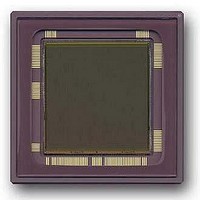
CYIL1SM4000-EVAL Cypress Semiconductor Corp, CYIL1SM4000-EVAL Datasheet - Page 31

CYIL1SM4000-EVAL
Manufacturer Part Number
CYIL1SM4000-EVAL
Description
BOARD EVAL IMAGE SENS LUPA-4000
Manufacturer
Cypress Semiconductor Corp
Specifications of CYIL1SM4000-EVAL
Sensor Type
CMOS Imaging, Monochrome
Sensing Range
4 Megapixel
Interface
SPI
Sensitivity
15 fps
Voltage - Supply
2.5 V ~ 3.3 V
Embedded
No
Utilized Ic / Part
LUPA-4000
Lead Free Status / RoHS Status
Contains lead / RoHS non-compliant
Lead Free Status / RoHS Status
Lead free / RoHS Compliant, Contains lead / RoHS non-compliant
LUPA-4000
Data Sheet
figure 15. This is the time to get the data stable from the pixels to the output bus
before the output stages. This ROT is in fact lost time and rather critical in a high-
speed sensor. Different timings to reduce this ROT are explained in next paragraph.
During the selection of 1 line, 2048 pixels are selected. These 2048 pixels have to be
readout by 1 (or 2) output amplifier.
Please note that the pixel rate is the double frequency of the Clock_x frequency. To
obtain a pixel rate of 66 MHz, one needs to apply a pixel clock Clock_x of 33MHz.
When only 1 analog output is used 2 pixels are output every Clock_x period. When
Clock_x is high, the first pixel is selected, when Clock_x is low, the next pixel is
selected. Consequently, during 1 complete period of Clock_x 2 pixels are readout by
the output amplifier.
If 2 analog outputs are used each Clock-X period 1 pixel is presented at each output.
Figure 16: X-addressing. From bottom to top: Clock_x, Sync_x, internal selection pixel 1&2, internal
selection pixel 3&4, internal selection pixel 5 & 6.
The first pixel that is selected is the x-address downloaded in the SPI. The starting
address is the number downloaded into the SPI, multiplied with 2.
Windowing is achieved by a starting address downloaded in the SPI and the size of
the window. In the x-direction, the size is determined by the moment a new Clock_y
is given. In the y-direction, the sync_y pulse determines the size. Consequently, the
best way to obtain a certain window is by using an internal counter in the controller.
Figure 16 is the simulation result after extraction of the layout module from a
different sensor to show the principle. In this figure the pixel clock has a frequency of
50MHz, which would result in a pixel rate of 100 Msamples/sec.
Figure 17 shows the relation between the applied Clock_x and the output signal.
Cypress Semiconductor Corporation
3901 North First Street
San Jose, CA 95134
408-943-2600
Contact:
info@Fillfactory.com
Document #: 38-05712 Rev.**(Revision 1.2 )
Page 31 of 49


