AT91EB40A Atmel, AT91EB40A Datasheet - Page 14
AT91EB40A
Manufacturer Part Number
AT91EB40A
Description
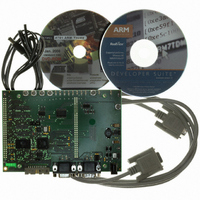
KIT EVAL FOR ARM AT91R40008
Manufacturer
Atmel
Series
AT91SAM Smart ARMr
Type
MCUr
Datasheet
1.AT91EB40A.pdf
(40 pages)
Specifications of AT91EB40A
Contents
Evaluation Board, Cable, Power Jack, CD-ROM
For Use With/related Products
AT91R40008
Lead Free Status / RoHS Status
Contains lead / RoHS non-compliant


2635C–ATARM–13-May-05
3.3
3.4
3-2
Programmed
Default Memory
Mapping
Flash Uploader
! When the SW3 button is pressed:
! The SW4 button is reserved for future use.
! When no buttons are pressed:
Table 3-1 defines the mapping defined by the boot program.
Table 3-1. Memory Map
Note:
U1A is divided in two parts. This is done by the jumper JP1. In the upper part, the first
sector (sector 24) at address 0x01100000 must be programmed with a boot sequence
to be debugged. This sector can be mapped at address 0x01000000 (or 0x0 after a
reset) when the jumper JP1 is in the USER position. See “Appendix A – Configuration
Straps” on page 5-1.
The Flash Uploader included in the EB40A Boot software is the same Flash Uploader
factory-programmed in the Flash-based AT91 devices, the AT91FR4042 and the
AT91FR40162/S. The Flash Uploader allows programming to the Sector 24of Flash
through a serial port. Either of the on-chip USARTs can be used by the Flash Uploader.
To boot from the application downloaded in the Sector 24, the downloading address
must be 0x01100000. Other sectors in plane B can be used to store constant data. The
boot starts the Flash Uploader if the SW3 button is pressed at reset.
The procedure is as follows:
1. Connect the Serial A (or B
2. Start the AT91Loader.exe program available in the AT91 Library on the host com-
3. Check JP1 is in STD position. Power-on or press RESET, holding down the SW3
Part Name
All the LEDs light up together.
The D3 LED remains lit when SW3 is released.
The Flash uploader is activated.
Branch at address 0x01006000.
The Angel Debug Monitor starts from this address by recopying itself in internal
SRAM.
PC Serial Port using the straight serial cable provided.
puter. The AT91 Loader must be configured beforehand. For more details, see
the documentation regarding the free Host Loader available for download on the
Atmel web site.
button simultaneously. Wait for all LEDs to light up together and then release
SW3. LED3 remains lit. If the AT91Loader is configured in automatic mode, the
download starts. Wait for the download to end.
U2 - U3
U1A
1. If fitted on the board
(1)
Start Address
0x01000000
0x02000000
(1)
) port of the AT91EB40A Evaluation Board to a host
End Address
0x011FFFFF
0x0203FFFF
AT91EB40A Evaluation Board User Guide
256K Bytes
2M Bytes
Size
AT49BV162A
Device
SRAM
Flash
Related parts for AT91EB40A
Image
Part Number
Description
Manufacturer
Datasheet
Request
R

Part Number:
Description:
DEV KIT FOR AVR/AVR32
Manufacturer:
Atmel
Datasheet:

Part Number:
Description:
INTERVAL AND WIPE/WASH WIPER CONTROL IC WITH DELAY
Manufacturer:
ATMEL Corporation
Datasheet:
Part Number:
Description:
Low-Voltage Voice-Switched IC for Hands-Free Operation
Manufacturer:
ATMEL Corporation
Datasheet:
Part Number:
Description:
MONOLITHIC INTEGRATED FEATUREPHONE CIRCUIT
Manufacturer:
ATMEL Corporation
Datasheet:
Part Number:
Description:
AM-FM Receiver IC U4255BM-M
Manufacturer:
ATMEL Corporation
Datasheet:
Part Number:
Description:
Monolithic Integrated Feature Phone Circuit
Manufacturer:
ATMEL Corporation
Datasheet:
Part Number:
Description:
Multistandard Video-IF and Quasi Parallel Sound Processing
Manufacturer:
ATMEL Corporation
Datasheet:
Part Number:
Description:
High-performance EE PLD
Manufacturer:
ATMEL Corporation
Datasheet:
Part Number:
Description:
8-bit Flash Microcontroller
Manufacturer:
ATMEL Corporation
Datasheet:
Part Number:
Description:
2-Wire Serial EEPROM
Manufacturer:
ATMEL Corporation
Datasheet: