AT91EB40A Atmel, AT91EB40A Datasheet - Page 19
AT91EB40A
Manufacturer Part Number
AT91EB40A
Description
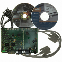
KIT EVAL FOR ARM AT91R40008
Manufacturer
Atmel
Series
AT91SAM Smart ARMr
Type
MCUr
Datasheet
1.AT91EB40A.pdf
(40 pages)
Specifications of AT91EB40A
Contents
Evaluation Board, Cable, Power Jack, CD-ROM
For Use With/related Products
AT91R40008
Lead Free Status / RoHS Status
Contains lead / RoHS non-compliant


4.6.2
4.7
AT91EB40A Evaluation Board User Guide
JTAG Interface
Layout Drawing
An ARM-standard 20-pin box header (P5) is provided to enable connection of an ICE to
the JTAG inputs on the AT91. This allows code to be debugged on the board without
using system resources, such as memory and serial ports.
The layout diagram (Figure 6-1 on page 6-2 in Section 6, “Appendix B – Schematics”)
shows an approximate floorplan for the board. This has been designed to give the low-
est board area, while still providing access to all test points, jumpers and switches on
the board.
The board is provided with four mounting holes, one at each corner, into which feet are
attached. The board has two signal layers and two power planes.
2635C–ATARM–13-May-05
4-3
Related parts for AT91EB40A
Image
Part Number
Description
Manufacturer
Datasheet
Request
R

Part Number:
Description:
DEV KIT FOR AVR/AVR32
Manufacturer:
Atmel
Datasheet:

Part Number:
Description:
INTERVAL AND WIPE/WASH WIPER CONTROL IC WITH DELAY
Manufacturer:
ATMEL Corporation
Datasheet:
Part Number:
Description:
Low-Voltage Voice-Switched IC for Hands-Free Operation
Manufacturer:
ATMEL Corporation
Datasheet:
Part Number:
Description:
MONOLITHIC INTEGRATED FEATUREPHONE CIRCUIT
Manufacturer:
ATMEL Corporation
Datasheet:
Part Number:
Description:
AM-FM Receiver IC U4255BM-M
Manufacturer:
ATMEL Corporation
Datasheet:
Part Number:
Description:
Monolithic Integrated Feature Phone Circuit
Manufacturer:
ATMEL Corporation
Datasheet:
Part Number:
Description:
Multistandard Video-IF and Quasi Parallel Sound Processing
Manufacturer:
ATMEL Corporation
Datasheet:
Part Number:
Description:
High-performance EE PLD
Manufacturer:
ATMEL Corporation
Datasheet:
Part Number:
Description:
8-bit Flash Microcontroller
Manufacturer:
ATMEL Corporation
Datasheet:
Part Number:
Description:
2-Wire Serial EEPROM
Manufacturer:
ATMEL Corporation
Datasheet: