AT91EB40A Atmel, AT91EB40A Datasheet - Page 21
AT91EB40A
Manufacturer Part Number
AT91EB40A
Description
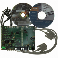
KIT EVAL FOR ARM AT91R40008
Manufacturer
Atmel
Series
AT91SAM Smart ARMr
Type
MCUr
Datasheet
1.AT91EB40A.pdf
(40 pages)
Specifications of AT91EB40A
Contents
Evaluation Board, Cable, Power Jack, CD-ROM
For Use With/related Products
AT91R40008
Lead Free Status / RoHS Status
Contains lead / RoHS non-compliant


5.1
AT91EB40A Evaluation Board User Guide
Configuration
Straps
By using the I/O and EBI expansion connectors, users can connect their own peripher-
als to the evaluation board. These peripherals may require more I/O lines than available
while the board is in its default state. Extra I/O lines can be made available by disabling
some of the on-board peripherals or features. This is done using the configuration straps
detailed below. Some of these straps present a default wire (notified by the default men-
tion) that must be cut before soldering the strap.
CB1
Closed
Open
CB2
1 - 2
2 - 3
CB3
Closed
Open
Appendix A – Configuration Straps
(2)
(1)
(1)
On-board CS4 Signal
AT91 CS4 signal is connected to the EBI expansion connector
(P1-B21).
AT91 CS4 signal is not connected to the EBI expansion connector (P1-B21).
This authorizes users to connect the EBI expansion connector of this board
to the MPI expansion connector of an AT91EB63 Evaluation Board without
conflict problems.
Core Power Supply Selection
The AT91 core is powered by 3.3V power supply. NOT ALLOWED for the
AT91R40008.
The AT91 core is powered by 1.8V power supply.
On-board Boot Chip Select
AT91 NCS0 select signal is connected to the Flash memory (U1A or U1B).
See also CB11.
AT91 NCS0 select signal is not connected to the Flash memory. This
authorizes users to connect the corresponding chip select signal to their own
resources via the EBI Expansion Connector.
Rev. 2635C–ATARM–13-May-05
Section 5
5-1
Related parts for AT91EB40A
Image
Part Number
Description
Manufacturer
Datasheet
Request
R

Part Number:
Description:
DEV KIT FOR AVR/AVR32
Manufacturer:
Atmel
Datasheet:

Part Number:
Description:
INTERVAL AND WIPE/WASH WIPER CONTROL IC WITH DELAY
Manufacturer:
ATMEL Corporation
Datasheet:
Part Number:
Description:
Low-Voltage Voice-Switched IC for Hands-Free Operation
Manufacturer:
ATMEL Corporation
Datasheet:
Part Number:
Description:
MONOLITHIC INTEGRATED FEATUREPHONE CIRCUIT
Manufacturer:
ATMEL Corporation
Datasheet:
Part Number:
Description:
AM-FM Receiver IC U4255BM-M
Manufacturer:
ATMEL Corporation
Datasheet:
Part Number:
Description:
Monolithic Integrated Feature Phone Circuit
Manufacturer:
ATMEL Corporation
Datasheet:
Part Number:
Description:
Multistandard Video-IF and Quasi Parallel Sound Processing
Manufacturer:
ATMEL Corporation
Datasheet:
Part Number:
Description:
High-performance EE PLD
Manufacturer:
ATMEL Corporation
Datasheet:
Part Number:
Description:
8-bit Flash Microcontroller
Manufacturer:
ATMEL Corporation
Datasheet:
Part Number:
Description:
2-Wire Serial EEPROM
Manufacturer:
ATMEL Corporation
Datasheet: