AT91EB55 Atmel, AT91EB55 Datasheet
AT91EB55
Specifications of AT91EB55
Available stocks


Related parts for AT91EB55


AT91EB55 Summary of contents
Page 1
... AT91EB55 Evaluation Board .............................................................................................. User Guide ...
Page 2
...
Page 3
... Layout .......................................................................................................2-1 2.4 Jumper Settings ........................................................................................2-2 2.5 Powering Up the Board .............................................................................2-2 2.6 Measuring Current Consumption on the AT91M55800A ..........................2-2 2.7 Testing the AT91EB55 Evaluation Board..................................................2-2 Section 3 The On-board Software ........................................................................ 3-1 3.1 AT91EB55 Evaluation Board ....................................................................3-1 3.2 The Boot Software Program......................................................................3-1 3.3 Programmed Default Memory Mapping ...
Page 4
... Power Consumption Measurement Straps (JP5, JP9) .............................5-4 5.3 Ground Links (JP6) ...................................................................................5-4 5.4 Increasing Memory Size ...........................................................................5-4 Section 6 Appendix B – Schematics..................................................................... 6-1 6.1 Schematics ...............................................................................................6-1 Section 7 Appendix C – Bill of Material ................................................................ 7-1 Section 8 Appendix D – Flash Memory ................................................................ 8-1 AT91EB55 Evaluation Board User Guide ...
Page 5
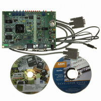
... Deliverables 1.3 The AT91EB55 Evaluation Board AT91EB55 Evaluation Board User Guide The AT91EB55 Evaluation Board enables real-time code development and evaluation. It supports the AT91M55800A. This user guide focuses on the AT91 Evaluation Board as an evaluation and demonstra- tion platform: ! Section 1 provides an overview. ...
Page 6
... Flash (of which available for user software bytes of Serial Data Flash (upgradeable pin EBI expansion connector ! pin I/O expansion connector ! 20-pin JTAG interface connector If required, user-defined peripherals can also be added to the board. See “Appendix A” for details. AT91EB55 Evaluation Board User Guide ...
Page 7
... Push Buttons Reset Controller Wake Up Push Button V and DDIO V DDCORE Power Supply 32.768 kHz XTAL Battery Power Supply AT91EB55 Evaluation Board User Guide AT91M55800 8K byte RAM ARM7TDMI EBI Processor ASB AMBA Clock Bridge Generator APB Interrupt PIO Controller Timer Watchdog Counters ...
Page 8
... Overview 1-4 1709C–ATARM–28-Apr-05 AT91EB55 Evaluation Board User Guide ...
Page 9
... Layout AT91EB55 Evaluation Board User Guide Setting Up the AT91EB55 The AT91EB55 Evaluation Board is shipped in protective anti-static packaging. The board must not be subjected to high electrostatic potentials. A grounding strap or similar protective device should be worn when handling the board. Avoid touching the compo- nent pins or any other metallic element. ...
Page 10
... DDCORE ments to be made on the current consumption of the AT91 product. See Appendix A for further details. In order to test the AT91EB55 Evaluation board, the following procedure should be performed: 1. Hold down the SW1 button and power up the board or generate a reset and wait for the light sequence on each LED to complete. All the LEDs light once and the D1 LED remains lit ...
Page 11
... D3 for the external Flash ! D4 reserved ! D5 for the SPI data flash ! D6 reserved ! D7 for the USART ! D8 for the ADC and DAC If a test is not carried out, the corresponding LED remains unlit and the test sequence restarts. Setting Up the AT91EB55 Evaluation Board 1709C–ATARM–28-Apr-05 2-3 ...
Page 12
... Setting Up the AT91EB55 Evaluation Board 2-4 1709C–ATARM–28-Apr-05 AT91EB55 Evaluation Board User Guide ...
Page 13
... AT91EB55 Evaluation Board User Guide The On-board Software The AT91EB55 Evaluation Board contains an AT49BV162A Flash device programmed with default software. Only the lowest eight 8-Kbyte sectors are used. The remaining sectors are user-definable and can be programmed using one of the Flash downloader solutions offered in the AT91 library ...
Page 14
... The boot program starts button is pressed. When Angel starts, it recopies itself in SRAM in order to run faster. The SRAM used by Angel is from 0x02020000 to 0x0203FFFF, i.e., the highest half part of the SRAM. The Angel on the AT91EB55 can be upgraded regardless of the version programmed on it. Note: If the debugger is started through ICE while the Angel monitor is on, the Advanced Interrupt Controller (AIC) and the USART channel are enabled ...
Page 15
... Connector 4.2.2 EBI Expansion Connector AT91EB55 Evaluation Board User Guide Figure 6-1 in “Appendix B – Schematics” shows the AT91M55800A. The footprint is for a 176-pin TQFP package. Strap CB15 enables the user to choose between the standard ICE debug mode and the JTAG boundary scan mode of operation. ...
Page 16
... Select Decode feature of the AT91 SPI peripheral (PCSDEC bit of the SPI Mode Register). Note: The AT91EB55 is fitted with two 128K x 8 SRAM devices and one AT45DB321 serial DataFlash device (U21)AT24C512. The AT24C512 64-Kbyte EEPROM, and AT25256 32-Kbyte EEPROM are not fitted. ...
Page 17
... Push Buttons, LEDs, Reset and Serial Interface AT91EB55 Evaluation Board User Guide Components for the PLL filter are fitted by default on the board (Figure 6-6 in "Appendix B – Schematics"). They are calculated to provide a 32 MHz (multiplier factor of 2 and settling time of 160 µs) Master Clock frequency. ...
Page 18
... See Figure 6-1 in “Appendix B – Schematics.” The board is provided with four mounting holes, one at each corner, into which feet are attached. The board has two signal layers and two power planes. AT91EB55 Evaluation Board User Guide ...
Page 19
... Configuration Straps (CB1 – 15, JP1 – 9) AT91EB55 Evaluation Board User Guide Appendix A – Configuration Straps By adding the I/O and EBI expansion connectors, users can connect their own peripher- als to the evaluation board. These peripherals may require more I/O lines than available while the board is in its default state ...
Page 20
... Boot Mode Strap Configuration (1) Open The BMS MCU input pin is set for the microcontroller to boot on an external 16-bit memory at reset. Closed The BMS MCU input pin is set for the microcontroller to boot on an external 8-bit memory at reset. AT91EB55 Evaluation Board User Guide ...
Page 21
... AT91EB55 Evaluation Board User Guide 2 CB13, CB14 I C EEPROM Enabling (1) 2 Closed E PROM communication is enabled. 2 Open E PROM communication is disabled. This authorizes users to connect the corresponding PIO to their own resources via the I/O expansion connector. CB15 JTAGSEL (1) 1 – 2 The MCU standard ICE debug feature is enabled. ...
Page 22
... APMC and RTC modules battery backup consumption (V The JP6 strap allows the user to connect the electrical and mechanical ground. The AT91EB55 evaluation board is supplied with two 128K bytes x 8 SRAM memories. If, however, the user needs more than 256K bytes of memory, the devices can be replaced with two 512K ...
Page 23
... AT91EB55 Evaluation Board User Guide Appendix B – Schematics The following schematics are appended: ! Figure 6-1 PCB Layout ! Figure 6-2 AT91EB55 Blocks Synopsis ! Figure 6-3 EBI Memories ! Figure 6-4 I/O and EBI Expansion Connectors ! Figure 6-5 Push Buttons, LEDs and Serial Interface ...
Page 24
... Appendix B – Schematics Figure 6-1. PCB Layout 128K x 8 512K x 8 128K x 8 512K x 8 6-2 1709C–ATARM–28-Apr-05 AT91M55800A 33 AI AT91EB55 Evaluation Board User Guide ...
Page 25
... Figure 6-2. AT91EB55 Blocks Synopsis AT91EB55 Evaluation Board User Guide SCL SDA SPCK MISO MOSI Appendix B – Schematics 6-3 1709C–ATARM–28-Apr-05 ...
Page 26
... Appendix B – Schematics Figure 6-3. EBI Memories 6-4 1709C–ATARM–28-Apr- AT91EB55 Evaluation Board User Guide ...
Page 27
... Figure 6-4. I/O and EBI Expansion Connectors AT91EB55 Evaluation Board User Guide Appendix B – Schematics 6-5 1709C–ATARM–28-Apr-05 ...
Page 28
... Appendix B – Schematics Figure 6-5. Push Buttons, LEDs and Serial Interface 6-6 1709C–ATARM–28-Apr- VCC AT91EB55 Evaluation Board User Guide 2 1 ...
Page 29
... TDI 166 167 168 169 CTL5 170 CTL3 171 NRD / NOE CTL2 172 CTL0 173 NWR1 / NUB CTL1 174 175 VDDIO 176 AT91EB55 Evaluation Board User Guide Appendix B – Schematics VDDIO NTRI / TXD1 / PA18 86 SCK1 / PA17 85 RXD0 / PA16 84 TXD0 / PA15 83 ...
Page 30
... Appendix B – Schematics Figure 6-7. Reset and JTAG Interface 14 7 6-8 1709C–ATARM–28-Apr- AT91EB55 Evaluation Board User Guide ...
Page 31
... Figure 6-8. Power Supply BOOST 1 GND 6 AT91EB55 Evaluation Board User Guide Appendix B – Schematics 6-9 1709C–ATARM–28-Apr-05 ...
Page 32
... Appendix B – Schematics Figure 6-9. SPI and TWI Memories 6-10 1709C–ATARM–28-Apr-05 Not Mounted 16 Not Mounted AT91EB55 Evaluation Board User Guide ...
Page 33
... AT91EB55 Evaluation Board User Guide Appendix C – Bill of Material Table 7-1. Bill of Material Item Qty Reference 1 1 BT1 2 2 CB16 3 3 CB18 C1, C2, C3, C4, C5, C12, C13, C16, C17, C18, C19, C22, C28, C29, C30, C31, C32, C36, C38, C39, C42 C49, C50, C51, C52, ...
Page 34
... Sub D 9b Male socket, right Sub angle, mechanical strength, locking HE10 2x10 socket, low profile, HE10 2x10 right angle 100K Resistor 5% 10K Resistor 5% 100R Resistor 5% 270K Resistor 5% 287R 1% E48 Resistor 1% Resistance network (4 resistors with 1 common point) 0R Shunt OR 100K Resistor 5% AT91EB55 Evaluation Board User Guide ...
Page 35
... AT91EB55 Evaluation Board User Guide Table 7-1. Bill of Material (Continued) Item Qty Reference SW1, SW2, SW3 SW4 43 1 SW5 TP1, TP2, TP3, TP4 ( U4 U10 52 1 U12 53 1 U13 54 2 U14, U15 55 1 U16 56 1 U30 57 2 U17, U18 58 1 U19 ...
Page 36
... Appendix C – Bill of Material 7-4 1709C–ATARM–28-Apr-05 AT91EB55 Evaluation Board User Guide ...
Page 37
... AT91EB55 Evaluation Board User Guide Appendix D – Flash Memory The Figure 8-1 shows the embedded software mapping after the remap. It describes the location for the different programs in the AT49BV162A flash memory and the division into sectors. Section 8 8-1 Rev. 1709C–ATARM–28-Apr-05 ...
Page 38
... Monitor 0x01006000 0x01005FFF Free Sector Boot Upgrade 0x01004000 0x01000000 Flash Uploader Functional Test Software Boot Program 15 Sectors 1MB (64K byte/sector) User Mode 15 Sectors (64K Byte/sector) 1MB Standard Mode 1 Sector (64K Byte/sector) 5 Sectors (8K Byte/sector) for 2 Sectors (8K Byte/sector) AT91EB55 Evaluation Board User Guide ...
Page 39
... Figure 6-3, AT49BV162A associated to U1 Table 6-9, name changed. U23 and U28 shown as “Not Mounted”. Table 7-1, item 46, parts column shows AT49BV162A-70TI Figure 8-1, illustration replaced AT91EB55 Evaluation Board User Guide Change Request Ref. CSR 05-199 PROM and SPI E PROM ...
Page 40
... Disclaimer: The information in this document is provided in connection with Atmel products. No license, express or implied, by estoppel or otherwise, to any intellectual property right is granted by this document or in connection with the sale of Atmel products. EXCEPT AS SET FORTH IN ATMEL’S TERMS AND CONDI- TIONS OF SALE LOCATED ON ATMEL’S WEB SITE, ATMEL ASSUMES NO LIABILITY WHATSOEVER AND DISCLAIMS ANY EXPRESS, IMPLIED OR STATUTORY WARRANTY RELATING TO ITS PRODUCTS INCLUDING, BUT NOT LIMITED TO, THE IMPLIED WARRANTY OF MERCHANTABILITY, FITNESS FOR A PARTICULAR PURPOSE, OR NON-INFRINGEMENT ...