AT91EB55 Atmel, AT91EB55 Datasheet - Page 20
AT91EB55
Manufacturer Part Number
AT91EB55
Description
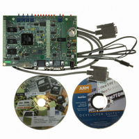
KIT EVAL FOR ARM AT91M55800A
Manufacturer
Atmel
Series
AT91SAM Smart ARMr
Type
MCUr
Datasheet
1.AT91EB55.pdf
(40 pages)
Specifications of AT91EB55
Contents
Evaluation Board, Cable, Power Jack, CD-ROM
For Use With/related Products
AT91M55800A
Lead Free Status / RoHS Status
Contains lead / RoHS non-compliant
Available stocks
Company
Part Number
Manufacturer
Quantity
Price


1709C–ATARM–28-Apr-05
Appendix A – Configuration Straps
5-2
CB4
Closed
Open
CB5
Closed
Open
CB6
Closed
Open
CB9
Closed
Open
CB10
Closed
Open
CB11
Open
Closed
(1)
(1)
(1)
(1)
(1)
(1)
Flash Reset
The on-board reset signal is connected to the Flash RESET input.
The on-board reset signal is not connected to the Flash RESET input.
Boot Mode Strap Configuration
The BMS MCU input pin is set for the microcontroller to boot on an external
16-bit memory at reset.
The BMS MCU input pin is set for the microcontroller to boot on an external
8-bit memory at reset.
On-board Boot Chip Select
users to connect the corresponding select signal to their own resources via the
EBI expansion connector.
Analog Converters Peripherals Loopback
DAC Channel 1 is connected to ADC Channel 0 for test purposes.
DAC Channel 1 is not connected to ADC Channel 0. This authorizes users to
connect the corresponding Analog Channels to their own resources via the I/O
expansion connector.
Analog Converter Peripherals Loopback
DAC Channel 0 is connected to ADC Channel 4 for test purposes.
DAC Channel 0 is not connected to ADC Channel 4. This authorizes users to
connect the corresponding Analog Channels to their own resources via the I/O
expansion connector.
Temperature Sensor Enabling
The temperature sensor device is connected to the ADC channel 1 (AD1)
input.
The temperature sensor device is not connected to the ADC channel 1 (AD1)
input. This authorizes users to connect the corresponding ADC channel to their
own resources via the I/O expansion connector.
NCS0 select signal is connected to the Flash memory.
NCS0 select signal is not connected to the Flash memory. This authorizes
AT91EB55 Evaluation Board User Guide
Related parts for AT91EB55
Image
Part Number
Description
Manufacturer
Datasheet
Request
R

Part Number:
Description:
DEV KIT FOR AVR/AVR32
Manufacturer:
Atmel
Datasheet:

Part Number:
Description:
INTERVAL AND WIPE/WASH WIPER CONTROL IC WITH DELAY
Manufacturer:
ATMEL Corporation
Datasheet:
Part Number:
Description:
Low-Voltage Voice-Switched IC for Hands-Free Operation
Manufacturer:
ATMEL Corporation
Datasheet:
Part Number:
Description:
MONOLITHIC INTEGRATED FEATUREPHONE CIRCUIT
Manufacturer:
ATMEL Corporation
Datasheet:
Part Number:
Description:
AM-FM Receiver IC U4255BM-M
Manufacturer:
ATMEL Corporation
Datasheet:
Part Number:
Description:
Monolithic Integrated Feature Phone Circuit
Manufacturer:
ATMEL Corporation
Datasheet:
Part Number:
Description:
Multistandard Video-IF and Quasi Parallel Sound Processing
Manufacturer:
ATMEL Corporation
Datasheet:
Part Number:
Description:
High-performance EE PLD
Manufacturer:
ATMEL Corporation
Datasheet:
Part Number:
Description:
8-bit Flash Microcontroller
Manufacturer:
ATMEL Corporation
Datasheet:
Part Number:
Description:
2-Wire Serial EEPROM
Manufacturer:
ATMEL Corporation
Datasheet: