AT91EB55 Atmel, AT91EB55 Datasheet - Page 22
AT91EB55
Manufacturer Part Number
AT91EB55
Description
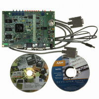
KIT EVAL FOR ARM AT91M55800A
Manufacturer
Atmel
Series
AT91SAM Smart ARMr
Type
MCUr
Datasheet
1.AT91EB55.pdf
(40 pages)
Specifications of AT91EB55
Contents
Evaluation Board, Cable, Power Jack, CD-ROM
For Use With/related Products
AT91M55800A
Lead Free Status / RoHS Status
Contains lead / RoHS non-compliant
Available stocks
Company
Part Number
Manufacturer
Quantity
Price


1709C–ATARM–28-Apr-05
Appendix A – Configuration Straps
5.2
5.3
5.4
5-4
Power
Consumption
Measurement
Straps (JP5, JP9)
Ground Links
(JP6)
Increasing
Memory Size
Note:
The JP5 strap enables the user to connect an ammeter to measure the AT91M55800A
global consumption (V
V
another ammeter between JP8 1 – 2 or 2 – 3 depending on the power supply used to
power the core.
The JP9 strap enables the user to connect an ammeter to measure the AT91M55800A
APMC and RTC modules battery backup consumption (V
The JP6 strap allows the user to connect the electrical and mechanical ground.
The AT91EB55 evaluation board is supplied with two 128K bytes x 8 SRAM memories.
If, however, the user needs more than 256K bytes of memory, the devices can be
replaced with two 512K x 8, 3.3V, 10/15 ns SRAMs, giving in total 1024K bytes.
The AT91EB55 evaluation board is supplied with one 4-MB Serial Data Flash. If the
user needs more storage memory, 3 additional footprints are provided to fit AT45DB321
devices giving a total of 16M bytes.
JP3
Open
Closed
JP7
Open
Closed
JP8
2 – 3
1 – 2
DDIO
(JP8 in 3V3 position). The user can measure the core consumption by connecting
1. Hardwired default position: To cancel this default configuration, cut (or place) the wire
(a jumper) on the board.
Core Power Supply Selection
The MCU core is powered by a 3.3V power supply.
Not supported on the current microcontroller revision.
Power Shut-down Feature
The power supply shut-down feature is disabled.
The power supply shut-down feature is enabled. The user may shut-down the
board main power supply by using the APMC shut-down feature. The system
may be awakened by pushing the S1 Wake-Up push button or by programming
an alarm in the RTC module.
RS-232 Driver Enabled
The RS-232 transceivers are enabled.
The RS-232 transceivers are disabled. This authorizes users to connect the
corresponding PIO to their own resources via the I/O expansion connector.
DDCORE
and V
DDIO
) when V
AT91EB55 Evaluation Board User Guide
DDCORE
DDBU
power supply is derived from
).
Related parts for AT91EB55
Image
Part Number
Description
Manufacturer
Datasheet
Request
R

Part Number:
Description:
DEV KIT FOR AVR/AVR32
Manufacturer:
Atmel
Datasheet:

Part Number:
Description:
INTERVAL AND WIPE/WASH WIPER CONTROL IC WITH DELAY
Manufacturer:
ATMEL Corporation
Datasheet:
Part Number:
Description:
Low-Voltage Voice-Switched IC for Hands-Free Operation
Manufacturer:
ATMEL Corporation
Datasheet:
Part Number:
Description:
MONOLITHIC INTEGRATED FEATUREPHONE CIRCUIT
Manufacturer:
ATMEL Corporation
Datasheet:
Part Number:
Description:
AM-FM Receiver IC U4255BM-M
Manufacturer:
ATMEL Corporation
Datasheet:
Part Number:
Description:
Monolithic Integrated Feature Phone Circuit
Manufacturer:
ATMEL Corporation
Datasheet:
Part Number:
Description:
Multistandard Video-IF and Quasi Parallel Sound Processing
Manufacturer:
ATMEL Corporation
Datasheet:
Part Number:
Description:
High-performance EE PLD
Manufacturer:
ATMEL Corporation
Datasheet:
Part Number:
Description:
8-bit Flash Microcontroller
Manufacturer:
ATMEL Corporation
Datasheet:
Part Number:
Description:
2-Wire Serial EEPROM
Manufacturer:
ATMEL Corporation
Datasheet: