AT91EB55 Atmel, AT91EB55 Datasheet - Page 16
AT91EB55
Manufacturer Part Number
AT91EB55
Description
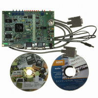
KIT EVAL FOR ARM AT91M55800A
Manufacturer
Atmel
Series
AT91SAM Smart ARMr
Type
MCUr
Datasheet
1.AT91EB55.pdf
(40 pages)
Specifications of AT91EB55
Contents
Evaluation Board, Cable, Power Jack, CD-ROM
For Use With/related Products
AT91M55800A
Lead Free Status / RoHS Status
Contains lead / RoHS non-compliant
Available stocks
Company
Part Number
Manufacturer
Quantity
Price


1709C–ATARM–28-Apr-05
Circuit Description
4.2.3
4.3
4.4
4.5
4-2
JTAG Interface
Memories
ADC and DAC
Peripheral
Connections
Power and
Crystal Quartz
An ARM-standard 20-pin box header (P5) is provided to enable connection of an ICE to
the JTAG inputs on the AT91. This allows code to be developed on the board without
using system resources such as memory and serial ports.
The schematics in Figure 6-3 and Figure 6-9 in "Appendix B – Schematics" show one
AT49BV162A 2-Mbyte 16-bit Flash, one AT24C512 64-Kbyte EEPROM, one AT25256
32-Kbyte EEPROM, two 128K/512K x 8 SRAM devices and four AT45DB321 4-Mbyte
serial data Flash devices.
The SPI devices are accessible through a 4 to 16 line decoder and by using the Chip
Select Decode feature of the AT91 SPI peripheral (PCSDEC bit of the SPI Mode
Register).
Note:
Strap JP1 shown on the schematic is used to select which part of 1-Mbyte of the flash is
to be accessed. This is to enable users to flash download their application in the second
part of the flash and to boot on it.
Two of the ADC and DAC channels are loop-backed together: DA0 on AD4 and DA1 on
AD0.
Two 2.5V voltage reference devices are fitted on the board and connected to the
DAVREF and ADVREF inputs, See Figure 6-6 in "Appendix B – Schematics". The user
can fit other voltage reference value devices from this family (REF19x from Analog
Devices) as the footprints are compatible.
A temperature sensor (LM61: Figure 6-6 in "Appendix B – Schematics") is connected to
the AD1 input and is placed near the 32.768 kHz crystal quartz. It enables the user to
take into account the frequency drift due to temperature evolutions using a software
program.
The V
This voltage can be measured by AD2 input and allows the user to select the running
clock accordingly.
The board features two quartz crystals: a 32.768 kHz one connected to the RTC low-
power oscillator of the AT91M55800A and a 16 MHz one connected to the main
oscillator.
The AT91M55800A Master Clock can be derived from the 32.768 kHz crystal quartz or
the 16 MHz crystal quartz depending on the programming of the APMC registers. The
on-chip oscillators together with one PLL-based frequency multiplier and the prescaler
results in a programmable Master Clock between 500 Hz and 33 MHz.
DDCORE
The AT91EB55 is fitted with two 128K x 8 SRAM devices and one AT45DB321 serial
DataFlash device (U21)AT24C512. The AT24C512 64-Kbyte EEPROM, and AT25256
32-Kbyte EEPROM are not fitted.
with a resistor bridge (10 k ) provides the following value:
VDDCORE
----------------------------- - c
2
AT91EB55 Evaluation Board User Guide
Related parts for AT91EB55
Image
Part Number
Description
Manufacturer
Datasheet
Request
R

Part Number:
Description:
DEV KIT FOR AVR/AVR32
Manufacturer:
Atmel
Datasheet:

Part Number:
Description:
INTERVAL AND WIPE/WASH WIPER CONTROL IC WITH DELAY
Manufacturer:
ATMEL Corporation
Datasheet:
Part Number:
Description:
Low-Voltage Voice-Switched IC for Hands-Free Operation
Manufacturer:
ATMEL Corporation
Datasheet:
Part Number:
Description:
MONOLITHIC INTEGRATED FEATUREPHONE CIRCUIT
Manufacturer:
ATMEL Corporation
Datasheet:
Part Number:
Description:
AM-FM Receiver IC U4255BM-M
Manufacturer:
ATMEL Corporation
Datasheet:
Part Number:
Description:
Monolithic Integrated Feature Phone Circuit
Manufacturer:
ATMEL Corporation
Datasheet:
Part Number:
Description:
Multistandard Video-IF and Quasi Parallel Sound Processing
Manufacturer:
ATMEL Corporation
Datasheet:
Part Number:
Description:
High-performance EE PLD
Manufacturer:
ATMEL Corporation
Datasheet:
Part Number:
Description:
8-bit Flash Microcontroller
Manufacturer:
ATMEL Corporation
Datasheet:
Part Number:
Description:
2-Wire Serial EEPROM
Manufacturer:
ATMEL Corporation
Datasheet: