101-1050 Rabbit Semiconductor, 101-1050 Datasheet - Page 116
101-1050
Manufacturer Part Number
101-1050
Description
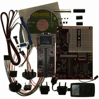
KIT DEV RABBITCORE RCM3750
Manufacturer
Rabbit Semiconductor
Series
RabbitCore 3000r
Type
MPU Moduler
Datasheet
1.20-101-1028.pdf
(172 pages)
Specifications of 101-1050
Contents
RabbitCore Module, Dev. Board, AC Adapter, Cable and Dynamic C® CD-Rom
Processor To Be Evaluated
RCM3750
Data Bus Width
8 bit
Interface Type
Ethernet
For Use With/related Products
RCM3750
Lead Free Status / RoHS Status
Contains lead / RoHS non-compliant
Other names
101-1049
101-1049
316-1117
Q2479714
Q2828455
101-1049
316-1117
Q2479714
Q2828455


B.2.1 Features
•
•
•
•
•
•
•
•
•
110
Power Connection
Note that the 3-pin header is symmetrical, with both outer pins connected to ground and
the center pin connected to the raw DCIN input. The cable of the AC adapter provided
with the North American version of the Ethernet Connection Kit ends in a plug that
connects to the power-supply header, and can be connected to the 3-pin header in either
orientation.
Users providing their own power supply should ensure that it delivers at least 200 mA
at 7.5–15 V DC. The voltage regulator will get warm while in use.
Linear Power Supply
routed to a 5 V linear voltage regulator. The regulator provides stable power to the
RCM3720 module and the Prototyping Board.
Power LED
Board.
Reset Switch
RCM3720’s
I/O Switches and LEDs
nected to the PF4 and PB7 pins of the RCM3720 module and may be read as inputs by
sample applications.
Two LEDs are connected to the PF6 and PF7 pins of the RCM3720 module, and may
be driven as output indicators by sample applications.
Prototyping Area
of through-hole components. +5 V and ground buses run along the bottom edge of this
area. Several areas for surface-mount devices are also available. (Note that there are
SMT device pads on both top and bottom of the Prototyping Board.) Each SMT pad is
connected to a hole designed to accept a 30 AWG solid wire or wire-wrap wire.
Module Extension Headers
cated at header J2. Developers can solder wires directly into the appropriate holes, or,
for more flexible development, a 2 × 20 header strip with a 0.1" pitch can be soldered
into place. See Figure B-14 for the header pinouts.
RS-232
mount RS-232 chip may be installed at U3. (Five 0.1 µF capacitors also need to be
added for the RS-232 circuit to work.) When stuffed, the RS-232 chip brings out Serial
Ports C and D to the header J3 area on the RCM3720 Prototyping Board. An optional
2 × 5 header strip with a 0.1" pitch can be installed at J3 to allow you to connect a rib-
bon cable that leads to a standard DB-9 serial connector.
Two 3-wire serial ports or one 5-wire RS-232 serial port are then available at header J3.
Backup Battery
battery backup for the RCM3720 SRAM and real-time clock.
—An optional through-hole RS-232 chip may be installed at U1 or a surface-
—The power LED lights whenever power is connected to the Prototyping
/RESET_IN
—A momentary-contact, normally open switch is connected directly to the
—A 2032 lithium-ion battery rated at 3.0 V, 220 mA·h, provides
—A generous prototyping area has been provided for the installation
—A 3-pin header is provided for connection to the power supply.
—The raw DC voltage provided at the POWER IN jack is
pin. Pressing the switch forces a hardware reset of the system.
—Two momentary-contact, normally open switches are con-
—The complete pin set of the RCM3720 module is dupli-
RabbitCore RCM3750
Related parts for 101-1050
Image
Part Number
Description
Manufacturer
Datasheet
Request
R

Part Number:
Description:
KIT DEV STANDARD RCM5700
Manufacturer:
Rabbit Semiconductor
Datasheet:

Part Number:
Description:
BL4S200 TOOL KIT
Manufacturer:
Rabbit Semiconductor
Datasheet:


Part Number:
Description:
KIT DEV FOR BL2500 COYOTE
Manufacturer:
Rabbit Semiconductor
Datasheet:

Part Number:
Description:
Microcontroller Modules & Accessories Keypad/Display Unit 5V Panel Mount
Manufacturer:
Rabbit Semiconductor

Part Number:
Description:
Single Board Computers 24VDC/110 Power Supp
Manufacturer:
Rabbit Semiconductor
Part Number:
Description:
MODULE RABBITCORE RCM3720
Manufacturer:
Rabbit Semiconductor
Datasheet:
Part Number:
Description:
MODULE RABBITCORE RCM3220
Manufacturer:
Rabbit Semiconductor
Datasheet:
Part Number:
Description:
MODULE RABBITCORE RCM3210
Manufacturer:
Rabbit Semiconductor
Datasheet:
Part Number:
Description:
COMPUTER SGL-BOARD OP6600 W/SRAM
Manufacturer:
Rabbit Semiconductor
Datasheet:
Part Number:
Description:
COMPUTER SGL-BD BL2000 SRAM/FLSH
Manufacturer:
Rabbit Semiconductor