101-1050 Rabbit Semiconductor, 101-1050 Datasheet - Page 14
101-1050
Manufacturer Part Number
101-1050
Description
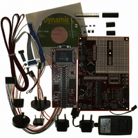
KIT DEV RABBITCORE RCM3750
Manufacturer
Rabbit Semiconductor
Series
RabbitCore 3000r
Type
MPU Moduler
Datasheet
1.20-101-1028.pdf
(172 pages)
Specifications of 101-1050
Contents
RabbitCore Module, Dev. Board, AC Adapter, Cable and Dynamic C® CD-Rom
Processor To Be Evaluated
RCM3750
Data Bus Width
8 bit
Interface Type
Ethernet
For Use With/related Products
RCM3750
Lead Free Status / RoHS Status
Contains lead / RoHS non-compliant
Other names
101-1049
101-1049
316-1117
Q2479714
Q2828455
101-1049
316-1117
Q2479714
Q2828455


2.2 Hardware Connections
There are three steps to connecting the Prototyping Board for use with Dynamic C and the
sample programs:
1. Attach the RCM3750 module to the Prototyping Board.
2. Connect the programming cable between the RCM3750 and the workstation PC.
3. Connect the power supply to the Prototyping Board.
The connections are shown for the RCM3700 Prototyping Board, and are similar for the
RCM3720 Prototyping Board.
2.2.1 Attach Module to Prototyping Board
Turn the RCM3750 module so that the Ethernet jack is on the left as shown in Figure 2
below. Insert the module’s J1 header into the TCM_SMT_SOCKET socket on the Proto-
typing Board. The shaded corner notch at the bottom right corner of the RCM3750 module
should face the same direction as the corresponding notch below it on the Prototyping
Board.
Press the module’s pins firmly into the Prototyping Board headers.
8
NOTE: It is important that you line up the pins on header J1 of the RCM3750 module
exactly with the corresponding pins of the TCM_SMT_SOCKET socket on the Proto-
typing Board. The header pins may become bent or damaged if the pin alignment is off-
set, and the module will not work. Permanent electrical damage to the module may also
result if a misaligned module is powered up.
Figure 2. Install the RCM3750 Module on the Prototyping Board
RabbitCore RCM3750
Related parts for 101-1050
Image
Part Number
Description
Manufacturer
Datasheet
Request
R

Part Number:
Description:
KIT DEV STANDARD RCM5700
Manufacturer:
Rabbit Semiconductor
Datasheet:

Part Number:
Description:
BL4S200 TOOL KIT
Manufacturer:
Rabbit Semiconductor
Datasheet:


Part Number:
Description:
KIT DEV FOR BL2500 COYOTE
Manufacturer:
Rabbit Semiconductor
Datasheet:

Part Number:
Description:
Microcontroller Modules & Accessories Keypad/Display Unit 5V Panel Mount
Manufacturer:
Rabbit Semiconductor

Part Number:
Description:
Single Board Computers 24VDC/110 Power Supp
Manufacturer:
Rabbit Semiconductor
Part Number:
Description:
MODULE RABBITCORE RCM3720
Manufacturer:
Rabbit Semiconductor
Datasheet:
Part Number:
Description:
MODULE RABBITCORE RCM3220
Manufacturer:
Rabbit Semiconductor
Datasheet:
Part Number:
Description:
MODULE RABBITCORE RCM3210
Manufacturer:
Rabbit Semiconductor
Datasheet:
Part Number:
Description:
COMPUTER SGL-BOARD OP6600 W/SRAM
Manufacturer:
Rabbit Semiconductor
Datasheet:
Part Number:
Description:
COMPUTER SGL-BD BL2000 SRAM/FLSH
Manufacturer:
Rabbit Semiconductor