101-1050 Rabbit Semiconductor, 101-1050 Datasheet - Page 121
101-1050
Manufacturer Part Number
101-1050
Description
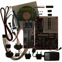
KIT DEV RABBITCORE RCM3750
Manufacturer
Rabbit Semiconductor
Series
RabbitCore 3000r
Type
MPU Moduler
Datasheet
1.20-101-1028.pdf
(172 pages)
Specifications of 101-1050
Contents
RabbitCore Module, Dev. Board, AC Adapter, Cable and Dynamic C® CD-Rom
Processor To Be Evaluated
RCM3750
Data Bus Width
8 bit
Interface Type
Ethernet
For Use With/related Products
RCM3750
Lead Free Status / RoHS Status
Contains lead / RoHS non-compliant
Other names
101-1049
101-1049
316-1117
Q2479714
Q2828455
101-1049
316-1117
Q2479714
Q2828455


A 2 × 4 header strip with a 0.1" pitch can be installed at J4, and jumpers across the appro-
priate pins on header J4 can be used to reconnect specific demonstration hardware later if
needed. Each pin is labeled on the PCB to facilitate placing the jumpers. The jumper posi-
tions are summarized in Table B-8.
B.2.4.1 Prototyping Area
There is a 1.8" × 2.4" through-hole prototyping space available on the RCM3720 Proto-
typing Board. The holes in the prototyping area are spaced at 0.1" (2.5 mm). +5 V and
ground traces run along the bottom edge of the prototyping area for easy access. Small to
medium circuits can be prototyped using point-to-point wiring with 20 to 30 AWG wire
between the prototyping area, the +5 V, and ground traces, and the surrounding area where
surface-mount components may be installed. Small holes are provided around the surface-
mounted components that may be installed around the prototyping area.
There are six sets of pads (three on each side) for 16-pin devices that can be used to surface-
mount SOIC devices. There are also pads that can be used for SMT resistors and capaci-
tors in an 0805 SMT package. Each component has every one of its pin pads connected to
a hole in which a 30 AWG wire can be soldered (standard wire-wrap wire can be soldered
in for point-to-point wiring on the RCM3720 Prototyping Board). Because the traces are
very thin, carefully determine which set of holes is connected to which surface-mount pad.
User’s Manual
Pins
1–2
3–4
5–6
7–8
Table B-8. RCM3720 Prototyping Board Jumper Settings
Signal Description
PB7
PF4
PF6
PF7
Header J4
Demonstration Hardware
Switch S1
Switch S2
LED DS1
LED DS2
115
Related parts for 101-1050
Image
Part Number
Description
Manufacturer
Datasheet
Request
R

Part Number:
Description:
KIT DEV STANDARD RCM5700
Manufacturer:
Rabbit Semiconductor
Datasheet:

Part Number:
Description:
BL4S200 TOOL KIT
Manufacturer:
Rabbit Semiconductor
Datasheet:


Part Number:
Description:
KIT DEV FOR BL2500 COYOTE
Manufacturer:
Rabbit Semiconductor
Datasheet:

Part Number:
Description:
Microcontroller Modules & Accessories Keypad/Display Unit 5V Panel Mount
Manufacturer:
Rabbit Semiconductor

Part Number:
Description:
Single Board Computers 24VDC/110 Power Supp
Manufacturer:
Rabbit Semiconductor
Part Number:
Description:
MODULE RABBITCORE RCM3720
Manufacturer:
Rabbit Semiconductor
Datasheet:
Part Number:
Description:
MODULE RABBITCORE RCM3220
Manufacturer:
Rabbit Semiconductor
Datasheet:
Part Number:
Description:
MODULE RABBITCORE RCM3210
Manufacturer:
Rabbit Semiconductor
Datasheet:
Part Number:
Description:
COMPUTER SGL-BOARD OP6600 W/SRAM
Manufacturer:
Rabbit Semiconductor
Datasheet:
Part Number:
Description:
COMPUTER SGL-BD BL2000 SRAM/FLSH
Manufacturer:
Rabbit Semiconductor