DEMO9S08EL32 Freescale Semiconductor, DEMO9S08EL32 Datasheet - Page 10
DEMO9S08EL32
Manufacturer Part Number
DEMO9S08EL32
Description
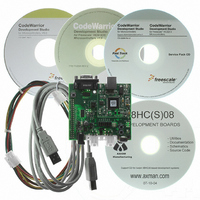
BOARD DEMO FOR 9S08 EL MCU
Manufacturer
Freescale Semiconductor
Type
MCUr
Datasheets
1.DEMO9S08EL32.pdf
(356 pages)
2.DEMO9S08EL32.pdf
(14 pages)
3.DEMO9S08EL32.pdf
(2 pages)
Specifications of DEMO9S08EL32
Contents
Evaluation Board
Processor To Be Evaluated
MC9S08EL32
Data Bus Width
8 bit
Interface Type
RS-232, USB
Operating Supply Voltage
12 V
Silicon Manufacturer
Freescale
Core Architecture
HCS08
Core Sub-architecture
HCS08
Silicon Core Number
MC9S08
Silicon Family Name
S08EL
Rohs Compliant
Yes
For Use With/related Products
MC9S08EL32
Lead Free Status / RoHS Status
Lead free / RoHS Compliant


D E M O 9 S 0 8 E L 3 2
U S E R
TIMING
The DEMO9S08EL32 is configured to use the target MCU’s internal clock source by default.
Space is provided for an external, 32 kHz XTAL oscillator; however, the external timing source
is not populated. The internal timing source is active out of RESET. Default configuration sets
the internal bus to run at 8.4MHz. The internal clock source is trimmable to ± 0.2%. Refer to
the MC9S08EL32 Data Sheet for further details.
COMMUNICATIONS
The DEMO9S08EL32 board applies a single Serial Communications Interface (SCI) port
configurable between either SCI or LIN functionality. RS-232 communications are supported
through a DB9 connector. LIN communications are supported through a pair of 4-pin Molex
connectors. A 2x3 option header selects the desired communications protocol.
RS-232
An RS-232 translator provides RS-232 to TTL/CMOS logic level translation on the COM
connector. The COM connector is a 9-pin Dsub, right-angle connector. A ferrite bead on
shield ground provides conducted immunity protection. Communication signals TXD and RXD
are routed from the transceiver to the MCU. Hardware flow control signals RTS and CTS are
available on the logic side of the transceiver. These signals are routed to vias located near the
transceiver.
Table 2 below details the SCI connections to the target MCU.
Table 2: COM Connections
COM Connector
A standard 9-pin Dsub connector provides external connections for the SCI0 port. The Dsub
shell is connected to board ground through a ferrite bead. The ferrite bead provides noise
isolation on the RS-232 connection. Figure 4 below details the DB9 connector pin-out.
Figure 4: COM Connector
G U I D E
MCU Port
PTB1/PIB1/SLTXD/TXD/ADP5
PTB0/PIB0/SLRXD/RXD/ADP4
GND
RXD
TXD
4, 6
1, 6
RTS has been biased properly to support 2-wire RS-232 communications.
1
2
3
4
5
6
7
8
9
1, 4
RTS
CTS
NC
Female DB9 connector that interfaces to the MCU internal SCI0 serial
port via the RS232 transceiver. Flow control is provided at test points on
the board.
Pins 1, 4, and 6 are connected together.
COM Signal
TXD
RXD
10
I/O PORT
CONNECTOR
J1-5
J1-7
A U G U S T
7 ,
2 0 0 8
Related parts for DEMO9S08EL32
Image
Part Number
Description
Manufacturer
Datasheet
Request
R

Part Number:
Description:
Manufacturer:
Freescale Semiconductor, Inc
Datasheet:
Part Number:
Description:
Manufacturer:
Freescale Semiconductor, Inc
Datasheet:
Part Number:
Description:
Manufacturer:
Freescale Semiconductor, Inc
Datasheet:
Part Number:
Description:
Manufacturer:
Freescale Semiconductor, Inc
Datasheet:
Part Number:
Description:
Manufacturer:
Freescale Semiconductor, Inc
Datasheet:
Part Number:
Description:
Manufacturer:
Freescale Semiconductor, Inc
Datasheet:
Part Number:
Description:
Manufacturer:
Freescale Semiconductor, Inc
Datasheet:
Part Number:
Description:
Manufacturer:
Freescale Semiconductor, Inc
Datasheet:
Part Number:
Description:
Manufacturer:
Freescale Semiconductor, Inc
Datasheet:
Part Number:
Description:
Manufacturer:
Freescale Semiconductor, Inc
Datasheet:
Part Number:
Description:
Manufacturer:
Freescale Semiconductor, Inc
Datasheet:
Part Number:
Description:
Manufacturer:
Freescale Semiconductor, Inc
Datasheet:
Part Number:
Description:
Manufacturer:
Freescale Semiconductor, Inc
Datasheet:
Part Number:
Description:
Manufacturer:
Freescale Semiconductor, Inc
Datasheet:
Part Number:
Description:
Manufacturer:
Freescale Semiconductor, Inc
Datasheet: