DEMO9S08EL32 Freescale Semiconductor, DEMO9S08EL32 Datasheet - Page 9
DEMO9S08EL32
Manufacturer Part Number
DEMO9S08EL32
Description
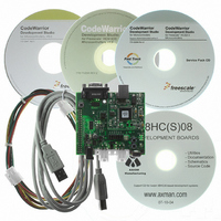
BOARD DEMO FOR 9S08 EL MCU
Manufacturer
Freescale Semiconductor
Type
MCUr
Datasheets
1.DEMO9S08EL32.pdf
(356 pages)
2.DEMO9S08EL32.pdf
(14 pages)
3.DEMO9S08EL32.pdf
(2 pages)
Specifications of DEMO9S08EL32
Contents
Evaluation Board
Processor To Be Evaluated
MC9S08EL32
Data Bus Width
8 bit
Interface Type
RS-232, USB
Operating Supply Voltage
12 V
Silicon Manufacturer
Freescale
Core Architecture
HCS08
Core Sub-architecture
HCS08
Silicon Core Number
MC9S08
Silicon Family Name
S08EL
Rohs Compliant
Yes
For Use With/related Products
MC9S08EL32
Lead Free Status / RoHS Status
Lead free / RoHS Compliant


D E M O 9 S 0 8 E L 3 2
A U G U S T
7 ,
2 0 0 8
U S E R
G U I D E
If powered from the PWR connector, the integrated BDM may still be used to develop and
debug application code. Alternately, the board may be powered from the integrated BDM
while the LIN bus is powered from the PWR connector.
VX_EN
The VX_EN option header is a 2-pin jumper that connects or disconnects input J1-1 directly to
the target board, +5V voltage rail. J1-3 is directly connected to the ground plane. Use of this
feature requires a regulated +5V input power source.
This power input is decoupled to
minimize noise but is not regulated. Care should be exercised when using this feature; no
protection is applied on this input and damage to the target board may result if over-driven.
Also, do not attempt to power the target board through this connector while also applying
power through the USB BDM or the PWR connector; damage to the board may result.
Power may also be sourced to off-board circuitry through the J1 connector. The current
supplied from the USB bus or the on-board regulator limits current available to external
circuitry. Excessive current drain may damage the target board, the host PC USB hub, or the
on-board regulator. Figure 3 below details the VX_EN header connections.
Figure 3: VX_EN Option Header
ON
OFF
1
2
Enabled
Disabled
VX_EN
CAUTION: Do not exceed available current supply from USB BDM or on-board regulator, when
sourcing power through connector J1 to external circuitry.
RESET SWITCH
The RESET switch applies an asynchronous RESET to the MCU. The RESET switch is
connected directly to the RESET* input on the MCU. Pressing the RESET switch applies a
low voltage level to the RESET* input. A pull-up bias resistor allows normal MCU operation.
Shunt capacitance ensures an adequate input pulse width.
LOW VOLTAGE RESET
The MC9S08EL32 utilizes an internal Low Voltage Detect (LVD) circuit. The LVD holds the
MCU in reset until applied voltage reaches an appropriate level. The LVD also protect against
under-voltage conditions. Consult the MC9S08EL32 reference manual for details LVD
operation.
9
Related parts for DEMO9S08EL32
Image
Part Number
Description
Manufacturer
Datasheet
Request
R

Part Number:
Description:
Manufacturer:
Freescale Semiconductor, Inc
Datasheet:
Part Number:
Description:
Manufacturer:
Freescale Semiconductor, Inc
Datasheet:
Part Number:
Description:
Manufacturer:
Freescale Semiconductor, Inc
Datasheet:
Part Number:
Description:
Manufacturer:
Freescale Semiconductor, Inc
Datasheet:
Part Number:
Description:
Manufacturer:
Freescale Semiconductor, Inc
Datasheet:
Part Number:
Description:
Manufacturer:
Freescale Semiconductor, Inc
Datasheet:
Part Number:
Description:
Manufacturer:
Freescale Semiconductor, Inc
Datasheet:
Part Number:
Description:
Manufacturer:
Freescale Semiconductor, Inc
Datasheet:
Part Number:
Description:
Manufacturer:
Freescale Semiconductor, Inc
Datasheet:
Part Number:
Description:
Manufacturer:
Freescale Semiconductor, Inc
Datasheet:
Part Number:
Description:
Manufacturer:
Freescale Semiconductor, Inc
Datasheet:
Part Number:
Description:
Manufacturer:
Freescale Semiconductor, Inc
Datasheet:
Part Number:
Description:
Manufacturer:
Freescale Semiconductor, Inc
Datasheet:
Part Number:
Description:
Manufacturer:
Freescale Semiconductor, Inc
Datasheet:
Part Number:
Description:
Manufacturer:
Freescale Semiconductor, Inc
Datasheet: