MPC8360E-RDK Freescale Semiconductor, MPC8360E-RDK Datasheet - Page 60
MPC8360E-RDK
Manufacturer Part Number
MPC8360E-RDK
Description
BOARD REFERENCE DESIGN FOR MPC
Manufacturer
Freescale Semiconductor
Series
PowerQUICC II™ PROr
Type
MPUr
Specifications of MPC8360E-RDK
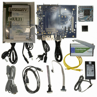
Contents
Board, Cables, CD, Power Supply
Processor To Be Evaluated
MPC8360E
Data Bus Width
32 bit
Interface Type
RS-232, Ethernet, USB
Operating Supply Voltage
1.3 V
For Use With/related Products
MPC8360E
Lead Free Status / RoHS Status
Lead free / RoHS Compliant


TDM/SI
Figure 42
generally reference the rising edge of the clock, these AC timing diagrams also apply when the falling edge
is the active edge.
Figure 42
Figure 43
17 TDM/SI
This section describes the DC and AC electrical specifications for the time-division-multiplexed and serial
interface of the MPC8360E/58E.
17.1
Table 57
60
Output high voltage
Output low voltage
Input high voltage
MPC8360E/MPC8358E PowerQUICC II Pro Processor Revision 2.x TBGA Silicon Hardware Specifications, Rev. 4
SPICLK (Output)
provides the DC electrical characteristics for the device TDM/SI.
Note: The clock edge is selectable on SPI.
Note: The clock edge is selectable on SPI.
TDM/SI DC Electrical Characteristics
Output Signals:
Output Signals:
SPICLK (Input)
and
shows the SPI timing in slave mode (external clock).
shows the SPI timing in Master mode (internal clock).
Input Signals:
Input Signals:
Characteristic
(See Note)
(See Note)
(See Note)
(See Note)
Figure 43
SPIMOSI
SPIMISO
SPIMISO
SPIMOSI
Figure 43. SPI AC Timing in Master Mode (Internal Clock) Diagram
Figure 42. SPI AC Timing in Slave Mode (External Clock) Diagram
represent the AC timing from
t
NEIVKH
Table 57. TDM/SI DC Electrical Characteristics
t
NIIVKH
Symbol
V
V
V
OH
OL
IH
t
NIKHOV
t
NIIXKH
t
NEKHOV
t
NEIXKH
I
OH
I
OL
Condition
Table
= –2.0 mA
= 3.2 mA
—
56. Note that although the specifications
Min
2.4
2.0
—
Freescale Semiconductor
OV
DD
Max
0.5
—
+ 0.3
Unit
V
V
V
Related parts for MPC8360E-RDK
Image
Part Number
Description
Manufacturer
Datasheet
Request
R

Part Number:
Description:
Mpc8360e Powerquicc Ii Pro Family
Manufacturer:
Freescale Semiconductor, Inc
Datasheet:

Part Number:
Description:
BOARD PROCESSOR FOR MPC8360E
Manufacturer:
Freescale Semiconductor
Datasheet:
Part Number:
Description:
Manufacturer:
Freescale Semiconductor, Inc
Datasheet:
Part Number:
Description:
Manufacturer:
Freescale Semiconductor, Inc
Datasheet:
Part Number:
Description:
Manufacturer:
Freescale Semiconductor, Inc
Datasheet:
Part Number:
Description:
Manufacturer:
Freescale Semiconductor, Inc
Datasheet:
Part Number:
Description:
Manufacturer:
Freescale Semiconductor, Inc
Datasheet:
Part Number:
Description:
Manufacturer:
Freescale Semiconductor, Inc
Datasheet:
Part Number:
Description:
Manufacturer:
Freescale Semiconductor, Inc
Datasheet:
Part Number:
Description:
Manufacturer:
Freescale Semiconductor, Inc
Datasheet:
Part Number:
Description:
Manufacturer:
Freescale Semiconductor, Inc
Datasheet:
Part Number:
Description:
Manufacturer:
Freescale Semiconductor, Inc
Datasheet:
Part Number:
Description:
Manufacturer:
Freescale Semiconductor, Inc
Datasheet:
Part Number:
Description:
Manufacturer:
Freescale Semiconductor, Inc
Datasheet:
Part Number:
Description:
Manufacturer:
Freescale Semiconductor, Inc
Datasheet: