HW-V5-ML501-UNI-G Xilinx Inc, HW-V5-ML501-UNI-G Datasheet - Page 27
HW-V5-ML501-UNI-G
Manufacturer Part Number
HW-V5-ML501-UNI-G
Description
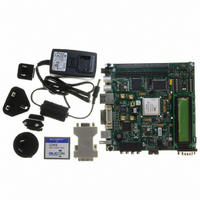
EVALUATION PLATFORM VIRTEX-5
Manufacturer
Xilinx Inc
Series
Virtex™-5 LXr
Type
FPGAr
Datasheet
1.HW-V5-ML501-UNI-G.pdf
(42 pages)
Specifications of HW-V5-ML501-UNI-G
Design Resources
ML501 Ref Design User Guide ML501 Schematics
Contents
ML501 Platform, DVI Adapter and CompactFlash Card
Silicon Manufacturer
Xilinx
Features
Programmable System Clock Generator Chip, RS-232 Serial Port
Silicon Family Name
Virtex-5
Silicon Core Number
XC5VLX50FFG676
Lead Free Status / RoHS Status
Lead free / RoHS Compliant
For Use With/related Products
XC5VLX50FFG676
Lead Free Status / RoHS Status
Lead free / RoHS Compliant, Lead free / RoHS Compliant
Other names
122-1508
Available stocks
Company
Part Number
Manufacturer
Quantity
Price


ML501 Evaluation Platform
UG226 (v1.4) August 24, 2009
17. System ACE and CompactFlash Connector
R
The Xilinx System ACE CompactFlash (CF) configuration controller allows a Type I
CompactFlash card to program the FPGA through the JTAG port. Both hardware and
software data can be downloaded through the JTAG port. The System ACE controller
supports up to eight configuration images on a single CompactFlash card. The
configuration address switches allow the user to choose which of the eight configuration
images to use.
The CompactFlash card shipped with the board is correctly formatted to enable the
System ACE CF controller to access the data stored in the card. The System ACE CF
controller requires a FAT16 file system, with only one reserved sector permitted, and a
sector-per-cluster size of more than one (UnitSize greater than 512). The FAT16 file system
supports partitions of up to 2 GB. If multiple partitions are used, the System ACE directory
structure must reside in the first partition on the CompactFlash, with the xilinx.sys file
located in the root directory. The xilinx.sys file is used by the System ACE CF
controller to define the project directory structure, which consists of one main folder
containing 8 sub-folders used to store the 8 ACE files containing the configuration images.
Only one ACE file should exist within each sub-folder. All folder names must be compliant
to the DOS 8.3 short filename format. This means that the folder names can be up to eight
characters long, and cannot contain the following reserved characters: < > “ / \ |. This
DOS 8.3 filename restriction does not apply to the actual ACE file names. Other folders and
files may also coexist with the System ACE CF project within the FAT16 partition.
However, the root directory must not contain more than a total of 16 folder and/or file
entries, including deleted entries.
When ejecting or unplugging the CompactFlash device, it is important to safely stop any
read or write access to the CompactFlash device to avoid data corruption. If the
CompactFlash file system becomes corrupted, a copy of the original demonstration image
(as shipped with the board), as well as instructions for re-imaging the CompactFlash card
to restore the original demonstration image are available online. See CompactFlash Re-
Imaging Instructions at http://www.xilinx.com/products/boards/ml501/images.htm.
Within the demonstration image, Configuration Image 6 (cfg6) My Own ACE File is reserved
as a placeholder to be replaced by a user design. After creating a new ACE file, the ACE file
can be copied from your computer to the ML50x\cfg6 directory on the CompactFlash card
using a CompactFlash programmer (USB CompactFlash reader/writer devices or PC card
adapters are available at computer stores). For step-by-step instructions on how to create a
new ACE file from an FPGA bitstream (and ELF file) using XMD and the genace.tcl
script, See the My Own ACE File section in the ML501 Getting Started Tutorial
well as the Stand-Alone Software Applications section in the ML501 Reference Design User
Guide
System ACE error and status LEDs indicate the operational state of the System ACE
controller:
•
•
•
•
Every time a CompactFlash card is inserted into the System ACE socket, a configuration
operation is initiated. Pressing the System ACE reset button re-programs the FPGA.
A blinking red error LED indicates that no CompactFlash card is present
A solid red error LED indicates an error condition during configuration
A blinking green status LED indicates a configuration operation is ongoing
A solid green status LED indicates a successful download
[Ref
11].
www.xilinx.com
Detailed Description
[Ref 10]
as
27
Related parts for HW-V5-ML501-UNI-G
Image
Part Number
Description
Manufacturer
Datasheet
Request
R

Part Number:
Description:
IC CPLD .8K 36MCELL 44-VQFP
Manufacturer:
Xilinx Inc
Datasheet:

Part Number:
Description:
IC CPLD 72MCRCELL 10NS 44VQFP
Manufacturer:
Xilinx Inc
Datasheet:

Part Number:
Description:
IC CPLD 1.6K 72MCELL 64-VQFP
Manufacturer:
Xilinx Inc
Datasheet:

Part Number:
Description:
IC CR-II CPLD 64MCELL 44-VQFP
Manufacturer:
Xilinx Inc
Datasheet:

Part Number:
Description:
IC CPLD 1.6K 72MCELL 100-TQFP
Manufacturer:
Xilinx Inc
Datasheet:

Part Number:
Description:
IC CR-II CPLD 64MCELL 56-BGA
Manufacturer:
Xilinx Inc
Datasheet:

Part Number:
Description:
IC CPLD 72MCRCELL 7.5NS 44VQFP
Manufacturer:
Xilinx Inc
Datasheet:
Part Number:
Description:
IC CR-II CPLD 64MCELL 100-VQFP
Manufacturer:
Xilinx Inc
Datasheet:
Part Number:
Description:
IC CPLD 1.6K 72MCELL 100-TQFP
Manufacturer:
Xilinx Inc
Datasheet:

Part Number:
Description:
IC CPLD 72MCRCELL 7.5NS 64VQFP
Manufacturer:
Xilinx Inc
Datasheet:
Part Number:
Description:
IC CPLD 1.6K 72MCELL 100-TQFP
Manufacturer:
Xilinx Inc
Datasheet:

Part Number:
Description:
IC CPLD 1.5K 64MCELL HP 44-VQFP
Manufacturer:
Xilinx Inc

Part Number:
Description:
IC CPLD 36MCRCELL 15NS 44PLCC
Manufacturer:
Xilinx Inc
Datasheet:

Part Number:
Description:
IC CPLD 36MCRCELL 10NS 44PLCC
Manufacturer:
Xilinx Inc
Datasheet:

Part Number:
Description:
IC CPLD 1.5K 64MCELL HP 44-VQFP
Manufacturer:
Xilinx Inc