101-0681 Rabbit Semiconductor, 101-0681 Datasheet - Page 103
101-0681
Manufacturer Part Number
101-0681
Description
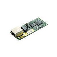
KIT DEVELOPMENT RCM3700 INT'L
Manufacturer
Rabbit Semiconductor
Series
RabbitCore 3000r
Type
MPU Moduler
Datasheet
1.101-0522.pdf
(169 pages)
Specifications of 101-0681
Contents
RabbitCore Module, Dev. Board, AC Adapter, Cable and Dynamic C® CD-Rom
Processor To Be Evaluated
Rabbit 3000
Interface Type
Ethernet
Maximum Operating Temperature
+ 70 C
Minimum Operating Temperature
- 40 C
Operating Supply Voltage
4.75 V to 5.25 V
For Use With/related Products
RCM3700
Lead Free Status / RoHS Status
Contains lead / RoHS non-compliant
Other names
101-681
101-681
101-681
Available stocks
Company
Part Number
Manufacturer
Quantity
Price
Company:

Part Number:
101-0681
Manufacturer:
Rabbit
Quantity:
201


B.1.5.3 Other A/D Converter Features
The A/D converter’s internal reference voltage is software-configurable for 1.15 V, 2.048 V,
or 2.5 V using the
library. The scaling circuitry on the Prototyping Board and the sample programs are
optimized for an internal reference voltage of 2.048 V. This internal reference voltage is
available on pin 3 of shrouded header J8 as VREF, and allows you to convert analog input
voltages that are negative with respect to analog ground.
The A/D converter’s CONVERT pin is available on pin 2 of shrouded header J8, and can
be used as a hardware means of forcing the A/D converter to start a conversion cycle. The
CONVERT signal is an edge-triggered event and has a hold time of two CCLK periods for
debounce.
A conversion is started by an active (rising) edge on the CONVERT pin. The CONVERT
pin must stay low for at least two CCLK periods before going high for at least two CCLK
periods. Figure B-7 shows the timing of a conversion start. The double falling arrow on
CCLK indicates the actual start of the conversion cycle.
RabbitCore RCM3700 User’s Manual
NOTE: The amplifier inside the A/D converter’s internal voltage reference circuit has a
very limited output-current capability. The internal buffer can source up to 20 mA and
sink only up to 20 µA. A separate buffer amplifier at U7 supplies the load current.
Figure B-7. Timing Diagram for Conversion Start Using CONVERT Pin
#define AD_OSC_ENABLE
macro in the Dynamic C
RCM37xx.LIB
101
Related parts for 101-0681
Image
Part Number
Description
Manufacturer
Datasheet
Request
R

Part Number:
Description:
COMPUTER SNGLBD BL2101 A/D 0-10V
Manufacturer:
Rabbit Semiconductor
Part Number:
Description:
CARD D/A 0-10V SR9400 SMARTSTAR
Manufacturer:
Rabbit Semiconductor
Datasheet:
Part Number:
Description:
CARD A/D 0-10V SR9300 SMARTSTAR
Manufacturer:
Rabbit Semiconductor
Datasheet:

Part Number:
Description:
WiFi / 802.11 Modules & Development Tools WIRELESS CONTROL APP KIT
Manufacturer:
Rabbit Semiconductor

Part Number:
Description:
KIT DEV RABBITCORE RCM3750
Manufacturer:
Rabbit Semiconductor
Datasheet:
Part Number:
Description:
KIT DEV RABBIT 2000 INT'L
Manufacturer:
Rabbit Semiconductor
Datasheet:
Part Number:
Description:
KIT DEV RABBIT RCM2000 INT'L
Manufacturer:
Rabbit Semiconductor
Datasheet:

Part Number:
Description:
BL4S200 TOOL KIT
Manufacturer:
Rabbit Semiconductor
Datasheet:

Part Number:
Description:
MODULE RABBITCORE RCM3720
Manufacturer:
Rabbit Semiconductor
Datasheet:
Part Number:
Description:
MODULE RABBITCORE RCM3220
Manufacturer:
Rabbit Semiconductor
Datasheet:
Part Number:
Description:
MODULE RABBITCORE RCM3210
Manufacturer:
Rabbit Semiconductor
Datasheet:
Part Number:
Description:
COMPUTER SGL-BOARD OP6600 W/SRAM
Manufacturer:
Rabbit Semiconductor
Datasheet:
Part Number:
Description:
COMPUTER SGL-BD BL2000 SRAM/FLSH
Manufacturer:
Rabbit Semiconductor