101-0681 Rabbit Semiconductor, 101-0681 Datasheet - Page 24
101-0681
Manufacturer Part Number
101-0681
Description
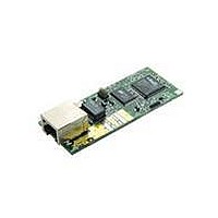
KIT DEVELOPMENT RCM3700 INT'L
Manufacturer
Rabbit Semiconductor
Series
RabbitCore 3000r
Type
MPU Moduler
Datasheet
1.101-0522.pdf
(169 pages)
Specifications of 101-0681
Contents
RabbitCore Module, Dev. Board, AC Adapter, Cable and Dynamic C® CD-Rom
Processor To Be Evaluated
Rabbit 3000
Interface Type
Ethernet
Maximum Operating Temperature
+ 70 C
Minimum Operating Temperature
- 40 C
Operating Supply Voltage
4.75 V to 5.25 V
For Use With/related Products
RCM3700
Lead Free Status / RoHS Status
Contains lead / RoHS non-compliant
Other names
101-681
101-681
101-681
Available stocks
Company
Part Number
Manufacturer
Quantity
Price
Company:

Part Number:
101-0681
Manufacturer:
Rabbit
Quantity:
201


3.2.3 A/D Converter Inputs
The following sample programs are found in the
•
•
•
•
•
•
•
RabbitCore RCM3700 User’s Manual
AD_CALDIFF_CH.C
channel using two known voltages to generate the calibration constants for that channel.
Constants will be rewritten into user block data area.
Before running this program, make sure that pins 1–3 are connected on headers JP5,
JP6, and JP7 on the Prototyping Board. No pins are connected on header JP8.
AD_CALMA_CH.C
convert analog current measurements to generate the calibration constants for that channel.
Before running this program, make sure that pins 3–5 are connected on headers JP5,
JP6, and JP7 on the Prototyping Board. Connect pins 1–2, 3–4, 5–6, 7–8 on header JP8.
AD_CALSE_ALL.C
channels for one gain, using two known voltages to generate the calibration constants
for each channel. Constants will be rewritten into the user block data area.
Before running this program, make sure that pins 3–5 are connected on headers JP5,
JP6, and JP7 on the Prototyping Board. No pins are connected on header JP8.
AD_CALSE_CHAN.C
channel with one gain using two known voltages to generate the calibration constants
for that channel. Constants will be rewritten into user block data area.
Before running this program, make sure that pins 3–5 are connected on headers JP5,
JP6, and JP7 on the Prototyping Board. No pins are connected on header JP8.
AD_RDDIFF_CH.C
differential input using previously defined calibration constants.
Before running this program, make sure that pins 1–3 are connected on headers JP5,
JP6, and JP7 on the Prototyping Board. No pins are connected on header JP8.
AD_RDMA_CH.C
vert analog current measurements using previously defined calibration constants for
that channel.
Before running this program, make sure that pins 3–5 are connected on headers JP5,
JP6, and JP7 on the Prototyping Board. Connect pins 1–2, 3–4, 5–6, 7–8 on header JP8.
AD_RDSE_ALL.C
using previously defined calibration constants.
Before running this program, make sure that pins 3–5 are connected on headers JP5,
JP6, and JP7 on the Prototyping Board. No pins are connected on header JP8.
NOTE: The above sample programs will overwrite any existing calibration constants.
—Demonstrates how to read an A/D input channel being used to con-
—Demonstrates how to recalibrate an A/D input channel being used to
—Demonstrates how to read all single-ended A/D input channels
—Demonstrates how to recalibrate all single-ended analog input
—Demonstrates how to read an A/D input channel being used for a
—Demonstrates how to recalibrate one differential analog input
—Demonstrates how to recalibrate one single-ended analog input
SAMPLES\RCM3700\ADC
folder.
22
Related parts for 101-0681
Image
Part Number
Description
Manufacturer
Datasheet
Request
R

Part Number:
Description:
COMPUTER SNGLBD BL2101 A/D 0-10V
Manufacturer:
Rabbit Semiconductor
Part Number:
Description:
CARD D/A 0-10V SR9400 SMARTSTAR
Manufacturer:
Rabbit Semiconductor
Datasheet:
Part Number:
Description:
CARD A/D 0-10V SR9300 SMARTSTAR
Manufacturer:
Rabbit Semiconductor
Datasheet:

Part Number:
Description:
WiFi / 802.11 Modules & Development Tools WIRELESS CONTROL APP KIT
Manufacturer:
Rabbit Semiconductor

Part Number:
Description:
KIT DEV RABBITCORE RCM3750
Manufacturer:
Rabbit Semiconductor
Datasheet:
Part Number:
Description:
KIT DEV RABBIT 2000 INT'L
Manufacturer:
Rabbit Semiconductor
Datasheet:
Part Number:
Description:
KIT DEV RABBIT RCM2000 INT'L
Manufacturer:
Rabbit Semiconductor
Datasheet:

Part Number:
Description:
BL4S200 TOOL KIT
Manufacturer:
Rabbit Semiconductor
Datasheet:

Part Number:
Description:
MODULE RABBITCORE RCM3720
Manufacturer:
Rabbit Semiconductor
Datasheet:
Part Number:
Description:
MODULE RABBITCORE RCM3220
Manufacturer:
Rabbit Semiconductor
Datasheet:
Part Number:
Description:
MODULE RABBITCORE RCM3210
Manufacturer:
Rabbit Semiconductor
Datasheet:
Part Number:
Description:
COMPUTER SGL-BOARD OP6600 W/SRAM
Manufacturer:
Rabbit Semiconductor
Datasheet:
Part Number:
Description:
COMPUTER SGL-BD BL2000 SRAM/FLSH
Manufacturer:
Rabbit Semiconductor